Dr. Charles D. Schlesinger discusses instrumentation that is more predictable and safe during the healing process

For years and for most practitioners, torque has been the gold standard for determining the stability of an implant. It has, and is, used to determine primary stability, integrated stability, and can be used to determine the minimum threshold when immediately loading dental implants.
[userloggedin]
Studies and anecdotal evidence have shown that 30 N/cm is the value considered to be sufficient for primary stability. Below this level, an implant has always been considered highly susceptible to failure by lack of stability. There are two types of torque that we see when placing an implant — insertion torque and seating torque. When immediately loading dental implants, it is the final insertion torque that is the key to successful treatment. In order to follow an immediate load protocol, a minimum seating torque value of 45 N/cm-50 N/cm is necessary.1

While torque values are useful and usually good predictors of success,2 we now have instrumentation that is more predictable and can be used safely during the healing process. This technology utilizes RFA, and the device is an Osstell IDx (Osstell, Sweden).
Not all patients are the same, and when we place an implant in a patient, the speed and extent to which they heal is highly variable from one individual to another. Wouldn’t it be nice to be able to monitor that healing process and know when you can restore rather than waiting for some generally advised average time period?
Torque
Webster’s Dictionary defines torque as a force to rotate an object about an axis (Figure 1). By Newton’s Third law of Motion, we can confidently deduce that the torque value a practitioner gets when placing an implant is equal to the resistance to the original rotational force. Basically, you can turn the implant, which is a screw, until it either cannot move axially in a downward direction anymore or the bone around the implant exceeds its deformational limit and can no longer resist the axial rotation (stripping). This deformational limit will vary from a high value in D1 cortical bone to a lower value in D4 medullary bone.

The limitation of just looking at torque is that it does not take into account the stability of the implant in lateral directions (Figure 2). It is this lateral stability, or resistance to sliding motion between the implant and the osteotomy, that is crucial to success. Therefore, it is possible to have a low torque value with high lateral stability or the opposite situation where you have high rotational stability (torque) and low lateral stability (ISQ).
A potentially devastating way to check integration has been the use of reverse torque to check an implant. The issue with this technique is that if the implant is integrating, yet not fully integrated, the use of reverse torque can unscrew an implant by breaking the integration that has already occurred. The result of this could jeopardize the success of the case or facilitate starting all over.
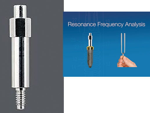
Resonance frequency analysis (RFA)
The use of RFA opens up a whole new possibility to be predictable not only in determining initial primary stability, but also the change in biologic stability that occurs as the osseointegrative process proceeds (Figure 3). With RFA, we can gently check the integration process without the potential for disturbing the integration process. The Osstell IDx uses a SmartPeg™ (Figure 4), which is screwed into the implant platform, and when pulsed by the transducer, it vibrates. This, in turn, is picked up by the receiver in the wand. This works on the same principle as a tuning fork (Figure 5). The tighter the implant is in bone, the higher the frequency vibration that is recorded when pulsed, and this is shown as a higher ISQ value.

The use and evaluation of ISQ allows the clinician to know what degree of initial mechanical lock the implant has. This mechanical lock is crucial to prevent detrimental micro-motion between the implant and the surrounding bone. According to the most recent literature published, an Osstell reading of 70 is desired for loading of an implant.3 Below this value, the lateral stability may not be high enough to resist a sliding motion of 150 microns. Movement greater than this will result in the formation of a soft tissue capsule and eventual failure of the implant.
The use of an implant designed for maximum mechanical lock into bone along with the use of RFA technology is a true game changer when treating implant patients.
Clinical case
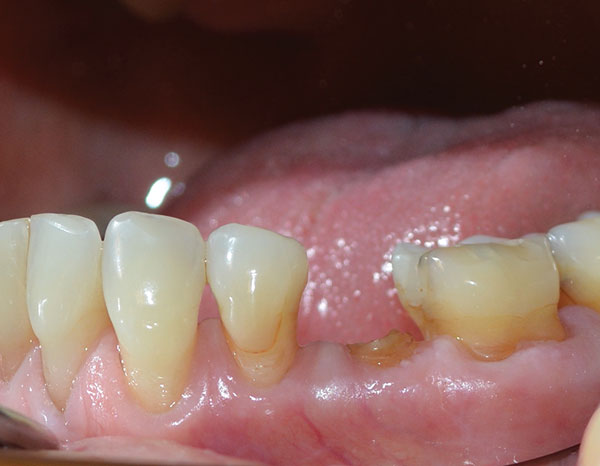
The patient who presented was a 64-year-old female with an unremarkable medical history other than a history of diagnosed osteoporosis without bisphosphonate usage. Her chief complaint was a fractured lower premolar. The tooth had the coronal tooth structure missing, previous endodontic treatment, and no infection was evident clinically or radiographically.

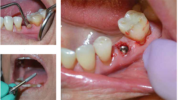
Preoperative CBCT showed the length of the root to be 10.3 mm from crest to apex with adequate vertical bone below the apex of the tooth (Figures 6-7). After profound soft and hard tissue anesthesia was established with an infiltrate of Septocaine® (Septodont USA), the root was atraumatically extracted utilizing periotomes, a spade proximator, and forceps (Figure 8). Once extracted, a curette was used to verify that the buccal wall was still intact and remove any remnants of the periodontal ligament. A high-speed handpiece and a long-shanked surgical carbide bur were then used to create a hole through the lingual lamina dura approximately ¾ of the way down the root socket. This provided a purchase point for the 1.8 mm pilot drill (Figure 9). An initial pilot hole was made to a depth of 15 mm from the remaining buccal crestal bone. Vertical position was verified using a depth stop on the pilot.
Utilizing the OCO Biomedical two-step drilling protocol, a proprietary 3.7 mm stepped final osteotomy former with a depth stop (Figure 10) was used to enlarge the pilot hole to the final osteotomy size. The step drill design of the osteotomy former performs the serial progression usually carried out by multiple burs in most systems. The non-end cutting drill also prevents over preparation of the osteotomy, which could affect the primary stability of the implant.

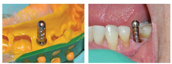
Once the osteotomy had been completed, a DBM allograft putty was placed against the buccal wall to fill in the gap that will be present once the implant is seated (Figure 11). Management of gaps larger than 2 mm is recommended. A 4.0 mm x 14 mm ENGAGE™ implant (OCO Biomedical) was placed (Figure 12) with the platform approximately 1 mm below the facial crest. This translates to the platform being approximately 3 mm below the current and intended FGM (Figures 13-14). A value of 30 N/cm was recorded for the final seating torque. This lower torque value was predicted due to the less than optimal bone quality (D4) based on the Hounsfield unit calculation of the CBCT. A SmartPeg was inserted into the implant, and ISQ values were taken in both the BL and MD directions. Both of the values were greater than 70 (Figure 15). Due to both values being above the minimum threshold for loading, the decision to load immediately despite a low seating torque value was made.

A PEEK abutment (Figure 16) was used along with a 3M Protemp™ crown to create a screw-retained temporary restoration (Figure 17). Chu, et al., has shown in the Dual Zone Management Model that the use of a temporary crown along with grafting of the buccal gap results in the least amount of hard and soft tissue changes.4 The contours of the temporary with its emergence profile, will maintain the soft tissue contours along with sealing the socket during healing. Once trimmed and polished, the temporary was replaced, and the fixation screw was tightened to finger tight — approximately 20 N/cm. The access hole was filled with a cotton pellet followed by flowable composite.

The patient was released after the 45-minute appointment and was followed up at 1-week and 1-month intervals. At the 1-month postoperative appointment, the temporary was removed, and an Osstell reading was taken. The ISQ value was recorded as 75 in both directions. Since this did not deviate dramatically from the initial values at placement, the decision to move forward with a final impression was carried out. An impression coping was placed, and a closed tray VPS full arch impression was taken (Figure 18). The impression coping was removed from the implant, screwed into an analog, and then it was placed back in the impression for fabrication of the final restoration by the lab (Figure 19). After recording a shade for the lab, the temporary abutment was replaced. The restorative phase is simplified with this system since all of the components (stock straight abutment, impression coping, and analog) come with the implant.
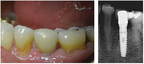
Two weeks later, the patient returned to the office for delivery of the final stock abutment and crown. The temporary crown was unscrewed, and an ISQ reading of 75 was recorded in all directions. The abutment was placed, and the abutment screw torqued to 30 N/cm. It was re-torqued after 10 minutes to accommodate any potential pre-stretch. The access hole was plugged with cotton and Cavit™ (3M), and the occlusion checked before final cementation with Improv® cement (Alvelogro). After removal of any excess cement, a final radiograph was taken to assure complete cleanup and seating of the crown (Figures 20-21), and the patient was dismissed.
Conclusion
Combining the stability challenges of immediate placement along with the compromised bone quality due to the patient’s previously diagnosed osteoporosis made this a less than ideal case. Without an implant designed for maximal bone engagement, even primary stability may not have been possible. If the decision to proceed with immediate loading would have been determined by looking at torque alone, this patient would have had a cover screw placed, and a 3-4 month healing period would have begun. Instead, she was immediately temporized and definitively restored in 6 weeks.
Though torque can be a great predictor of stability, it is limited in its scope. It is like comparing a 2D pan to a 3D CBCT. Both work, but the one with the advancement in technology provides a far more accurate assessment of the situation. If you want to place implants at the highest level and provide your patients with the best care available, then there is no reason not to utilize the very best implant and the very best technology to assure your success and your patients’ satisfaction.
[/userloggedin]
[userloggedout][/userloggedout]
 Charles Schlesinger, DDS, FICOI, an internationally renowned implant educator for the past 9 years, graduated from The Ohio State University College of Dentistry in 1996. After completing a General Practice Residency at the VAMC San Diego, he went on to become the Chief Resident of the GPR Program at the VAMC West Los Angeles. During his time in L.A., he received extensive training in oral surgery, implantology, and complex restorative dentistry. Dr. Schlesinger maintained a thriving practice in San Diego for 14 years before he relocated with his family to Albuquerque to become the Director of Education and Clinical Affairs for OCO Biomedical. In 2013, he became the Chief Operating Officer in addition to his clinical duties at OCO.
- Schlesinger CD. Immediately loading dental implants: doing it right for long term success. Dent Today. 2016;35(5):84-89.
- Anitua E, Piñas L, Alkhraisat MH. Long-term outcomes of immediate implant placement into infected sockets in association with immediate loading: a retrospective cohort study. J Periodontol. 2016;13:1-15.
- Kokovic V, Jung R, Feloutzis A, Todorovic VS, Jurisic M, Hämmerle CH. Immediate vs. early loading of SLA implants in the posterior mandible: 5-year results of randomized controlled clinical trial. Clin Oral Implants Res. 2104;25(2):e114-119.
- Chu SJ, Salama MA, Salama H, Garber DA, Saito H, Sarnachiaro GO, Tarnow DP. The dual-zone therapeutic concept of managing immediate implant placement and provisional restoration in anterior extraction sockets. Compend Contin Educ Dent. 2012;33(7):524-532,534.
Stay Relevant With Implant Practice US
Join our email list for CE courses and webinars, articles and mores