Dr. Farhad E. Boltchi provides a step-by-step overview of his digital workflow

Introduction
Sirona’s CEREC-GALILEOS integration workflow provides a completely integrated digital implant dentistry workflow incorporating all aspects of surgical and restorative implant dentistry. This article will provide a step-by-step overview of this digital workflow.
[userloggedin]
Case example

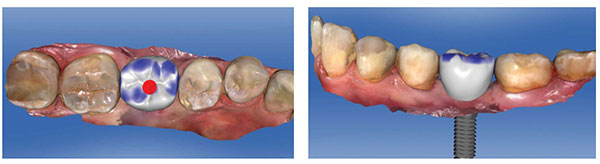
This patient is a 38-year-old male patient with a noncontributory medical history, who presented for implant therapy to replace missing tooth No. 19. The initial clinical and periapical radiographic evaluation revealed an edentulous site with clinically adequate ridge width and with adequate bone and soft tissue volume for dental implant therapy (Figures 1-2).
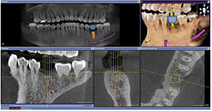
A cone beam CT radiographic evaluation was performed with the Sirona Orthophos XG 3D CBCT machine, and a digital impression of the patient’s maxillary and mandibular arches was obtained via scanning with the CEREC Omnicam. A virtual restoration was then designed in the CEREC Chairside software, and the corresponding CAD/CAM data was exported into the GALILEOS Implant treatment planning software, where it was merged with the CBCT scan. The GALILEOS Implant treatment planning software was utilized to plan a BioHorizons®
Tapered Internal Plus 5.8 mm x 12 mm implant in site No. 19 (Figure 3). The treatment planning data was then exported from the GALILEOS Implant treatment planning software and sent to SiCat in Bonn, Germany for the design and fabrication of a SICAT OPTIGUIDE surgical guide (Figure 4).
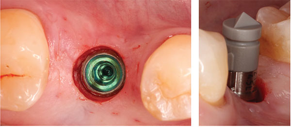
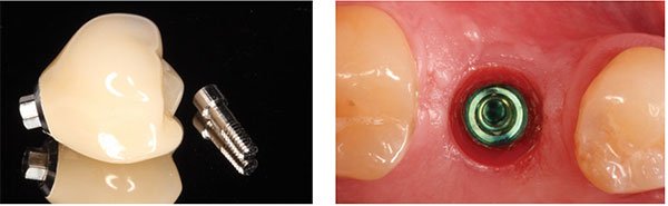
The surgical procedure was performed under local anesthesia, and implant placement in site No. 19 was accomplished via a flapless guided approach. The SICAT OPTIGUIDE and the BioHorizons guided surgery system were then utilized to prepare the guided implant osteotomy according to the virtual treatment plan in the GALILEOS Implant software, and a BioHorizons Tapered Internal Plus 5.8 mm x 12 mm implant was placed through the SICAT OPTIGUIDE in a fully guided fashion in the restoratively correct and preplanned position (Figures 5-12). The implant achieved excellent primary stability and was placed in a flapless approach within the confines of the osseous alveolar housing (Figure 13). A Sirona ScanPost and the corresponding Scanbody were then inserted onto the implant, and a CEREC Omnicam digital impression/scan of the Scanbody was obtained to allow for the fabrication of a screw-retained provisional restoration while the implant was undergoing the osseointegration healing phase (Figure 14). In order to start developing the implant tissue transition zone, a wide healing abutment was then placed on the implant (Figures 15-16).


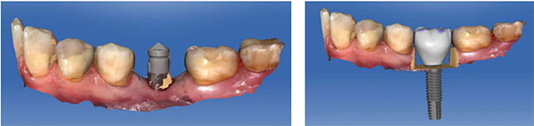
Based on the CEREC Omnicam digital impression/scan of the Scanbody, a full-contour screw-retained crown was designed in the CEREC chairside software (Figures 17-21). The corresponding custom screw-retained provisional restoration was then milled out of an Ivoclar Vivadent® Implant Solutions Telio® CAD A16 block, adjusted and polished, and then bonded to a Sirona TiBase with Ivoclar Vivadent’s Multilink® Hybrid Abutment cement (Figure 22). After an uneventful healing period of 8 weeks, this custom screw-retained provisional restoration was screwed onto the implant to develop the ideal peri-implant soft tissue profile (Figures 23-25).


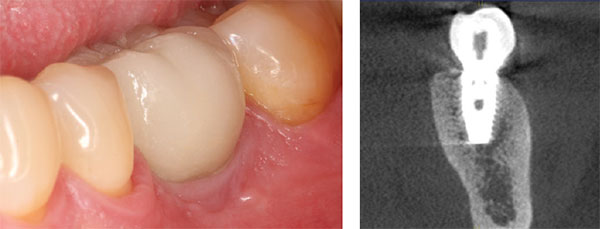
After an additional 3 weeks, the previous digital full-contour design in the CEREC software was used to fabricate the final implant restoration as a split custom abutment with a cemented final implant crown. The final clinical, periapical radiographic, and CBCT radiographic evaluation revealed an optimal hard and soft tissue integration of the final implant-supported restoration (Figures 26-27).

Discussion
This case report demonstrates the high degree of precision and efficiency that can be achieved with the CEREC-GALILEOS integration digital implant dentistry workflow. In an ideal scenario such as the case described previously, the entire implant treatment can be accomplished in two-to-three appointments. The first appointment would consist of a preoperative digital impression, virtual implant planning, guided implant placement, digital impression of the implant, and the digital fabrication of a custom provisional implant restoration as needed. The second appointment would be optional and would consist of the insertion of the custom provisional restoration for the development of the peri-implant tissue transition zone as needed. The third appointment would then consist of the in-house digital fabrication of the final implant restoration without the need for an additional digital impression, removal of the provisional restoration, and the insertion of the final implant restoration.
[/userloggedin]
[userloggedout][/userloggedout]
 Farhad E. Boltchi, DMD, MS, is in private practice limited to periodontics and dental implants in Arlington, Texas, and is Clinical Assistant Professor, Graduate Periodontics Program, at the Texas A&M University College of Dentistry in Dallas, Texas. He is a Diplomate of the American Board of Periodontology and a Fellow of the International Team for Implantology (ITI).
Stay Relevant With Implant Practice US
Join our email list for CE courses and webinars, articles and mores