Educational aims and objectives
This self-instructional course for dentists aims to discuss a CBCT-guided technology to facilitate indirect (crestal) sinus lift with immediate dental implant placement.
Expected outcomes
Implant Practice US subscribers can answer the CE questions by taking the quiz to earn 2 hours of CE from reading this article. Correctly answering the questions will demonstrate the reader can:
- Realize some history and variations in the technique of sinus lift and bone grafting for facilitating dental implant placement.
- Realize the greater accuracy of alveolar ridge height measurement that can be achieved when using cone beam CT (CBCT) as the imaging modality.
- Identify other devices and instruments that have been used to minimize risk of tearing the sinus membrane in both lateral wall and crestal sinus lift techniques.
- Realize the benefit of a surgical guide based on the prosthetic plan to determine optimal location for implant placement as well as improving accuracy of the osteotomy position.
- Read about a patient whose treatment reflects the author’s chosen technique.
Dr. Jay Reznick describes a procedure using CBCT that is predictable, time-efficient, minimally invasive, comfortable for the patient — and successful!
Dr. Jay Reznick introduces a novel, predictable, time-efficient, minimally invasive technique
Introduction
Ridge resorption begins immediately after a tooth is removed. In the posterior maxillary arch, this bone loss is compounded by pneumatization of the maxillary sinus into the edentulous space. Even when ridge preservation is performed, the residual alveolar ridge may be deficient for dental implant placement due to inferior expansion of the sinus floor. This can be managed by sinus augmentation, either by a lateral or crestal approach. Many techniques have been developed for the crestal sinus lift utilizing various osteotomes, bone compactors, and drilling systems with control devices to limit depth of penetration toward the sinus floor to avoid tearing of the sinus membrane. This report describes a unique technique that utilizes CBCT-guided surgery to develop a controlled osteotomy to accomplish a crestal sinus lift.
Once teeth have been removed, the bony resorption process begins. Lack of functional stresses on the alveolar bone leads to a decrease in density at the extraction site and its surrounding bone.1,2 In the maxillary posterior region, there are two opposing forces at work that can severely compromise the alveolar ridge volume in the site where a dental implant is to be placed. Alveolar ridge resorption has been well documented and is greatest in the first 3 to 6 months following tooth removal. Two-thirds of the resorption occurs within the first few months. Bone of the alveolar ridge diminishes both in width and height.3,4 It has also been demonstrated that immediate ridge preservation grafting of the extraction site significantly reduces the amount of alveolar volume reduction in the first 6 months.5,6,7 From the maxillary second premolar to the second molar, once a tooth has been removed from this region, the process of pneumatization of the sinus begins. This is variable from patient to patient and has been shown by Sharan and Madjar8 that this is most problematic in patients who have a superiorly curving sinus floor above the extracted tooth, for the second-premolar and first-molar teeth, and when the sinus appeared to already be pneumatized around the roots.9
Even before dental implants were mainstream dentistry, ridge atrophy and expansion of the sinus have made prosthetic restoration of the edentulous maxillary arch more difficult. In order to reduce the bone loss caused by pneumatization of the sinus, Boyne in 1960, in a lecture to U.S. Navy postgraduate dental students10 suggested bone grafting to the floor of the maxillary sinus in order to increase the inter-arch distance in longstanding edentulous patients. The technique of sinus lift and bone grafting for facilitating dental implant placement was first described by Tatum at the Alabama Implant Congress meeting in 1976. In 1980, Boyne and James published their technique.11 This was essentially a modification of the maxillary wall osteotomy described by George Caldwell and Henry Luc in the 19th century, used to gain access for treating sinus disease, except that the Schneiderian membrane was elevated from the sinus floor to create a pocket for bony regeneration and subsequent dental implant placement.12 This technique, known as the “lateral wall“ or “open” sinus lift, has been used now for decades and has a very high success rate with a low morbidity.13 It is most useful when there is less than 5 millimeters of residual bone between the sinus floor and maxillary alveolar ridge crest,14,15 or when multiple implants will be placed in the posterior atrophic maxilla.
The lateral wall technique of sinus lift was popular among oral and maxillofacial surgeons, but rarely used by other dental practitioners due to the technical aspects of the procedure. In order to create a less invasive procedure with reduced morbidity, a new technique was introduced by Robert Summers at the 1993 Academy of Osseointegration meeting16 utilizing a pilot drill via a crestal approach, driven 1 millimeter short of the sinus floor. Calibrated tapered osteotomes were then applied in sequence of increasing diameter in order to shave bone and push it toward the end of the osteotomy, and then up-fracture a 1 mm thick section of the sinus floor. This would elevate the sinus membrane to develop a space for placement of additional bone graft and a dental implant. This technique is best suited when 5 mm or greater height of crestal bone is present, allowing simultaneous implant placement at the time of sinus lift.
Over the years, there have been many modifications of Summers’ technique developed to reduce the risk of perforation of the sinus membrane via crestal approach. Pontes used a connective tissue graft taken from the hard palate to cushion the Summers No. 2 sinus floor elevator when up-fracturing the bone at the superior end of the osteotomy.16 Various “sinus lift” surgical kits have been created to simplify the crestal sinus lift.17,18 Bernardello, et al., described using Cosci’s technique19 with 3.1 mm diameter drills of various lengths from 2 mm to 12 mm, based on the ridge height measurement to prepare the osteotomy. These drills had a non-fluted tip that prevented perforation of the sinus membrane by abrasive removal of the bony sinus floor. The final drill length was selected to stop 1 mm below the sinus floor. An intraoral radiograph with a parallel pin was used to verify the depth. Next, a “lifting drill” that was 1 mm longer than the measured crest height was used to perforate the sinus floor. A self-tapping implant of approximately 3.5 mm to 3.75 mm diameter was then inserted into the osteotomy.20
Drew, et al., described using a surgical guide made from study models and a diagnostic wax-up to direct the initial osteotome, as well as subsequent osteotomes of increasing diameter, tapped 1 mm – 2 mm inferior to the sinus floor.21 Their reason for using a guide was that they felt that subsequent osteotomies could deviate from the path of the initial instrument. Bone graft material was placed into the final osteotomy and then tapped superiorly with the final osteotome to elevate the sinus floor and membrane. Additional bone graft is pushed through the osteotomy with the final osteotome to the desired volume increase, and the implant is then inserted into place. They concluded that it was imperative to use a guide, especially when the volume of alveolar ridge bone is limited.
All of the preceding methods planned the osteotomies by measuring the height of the alveolar ridge from a two-dimensional radiograph and drilling just short of the sinus floor. Much greater accuracy of alveolar ridge height measurement can be achieved when using cone beam CT (CBCT) as the imaging modality.22 Checchi, et al., compared the Cosci and Summers techniques by treating 15 bilaterally partially edentulous patients with each technique in a split-mouth design. Patients were treatment-planned based on CBCT, although no mention was made as to why this was chosen over two-dimensional images.23 Thomas and Bindra emphasized the use of CBCT imaging to evaluate the ridge height and width, as well as the anatomy of the sinus above the implant site. They again described use of “careful drilling without perforation of the sinus floor” to prepare the osteotomy using sequentially wider drills. They did not use any bone graft placed in the sinus floor, but placed a collagen plug to protect against microtears of the membrane as it was elevated.24
Other devices and instruments have been used to minimize risk of tearing the sinus membrane in both lateral wall and crestal sinus lift techniques. The balloon sinus lift is generally used through the crestal approach.25 A catheter with an elastic balloon at the tip is introduced into the sinus once the bony floor has been penetrated. The balloon is filled with sterile saline and is used to gently lift the sinus membrane from the sinus floor using hydraulic pressure. Bone graft is then introduced through the osteotomy prior to implant placement. Troedhan, et al., introduced a technique using a piezosurgery unit and a specially designed set of tips and reported their results on 404 patients.26 After drilling with a pilot drill to 2 mm below the sinus floor, the osteotomy is widened with the calibrated diamond tips and deepened to the sinus floor. Finally. A “trumpet” tip is used to elevate the sinus membrane and to create a space for a bone graft and the implant. In a human cadaver study, none of the 150 specimens showed perforation of the membrane using this technique.27 All these techniques have shown similar success rates no matter which protocol is used.
Now that CBCT has become the de facto standard of care for dental implant planning, many clinicians have developed crestal sinus lift techniques that exploit the dimensional accuracy of the 3D image compared to a 2D radiograph and its ability to assess sinus anatomy and health.22 A surgical guide based on the prosthetic plan helps to determine optimal location for implant placement, as well as improving accuracy of the osteotomy position. Chasioti, et al., reported on a staged technique utilizing these principles and concluded that despite the knowledge, time, and effort needed to plan and use a guide, the final prosthetic outcome is more predictable and successful.28 Attanasio, et al., used a series of manual screw-tapered bone expanders through a flapless crestal approach to create the implant osteotomy and atraumatically lift the sinus membrane. Surgery was planned using implant planning software, merging the CBCT data with an intraoral optical scanning image to create a prosthetically based surgical guide. They proposed that this type of flapless, guided technique leads to better accuracy, and decreased surgical time and patient discomfort.29 Solano, et al., reported a case of transcrestal sinus lift and implant placement using CBCT, CAD/CAM technology and implant planning software to determine optimal implant diameter, length, and placement. They used a printed surgical guide to drill to 1 mm below the sinus floor, followed by penetration of the sinus floor and elevation of the Schneiderian membrane with specially designed rotary instruments. A cortico-cancellous allograft was placed, followed by the implant fixture, which was delivered to the proper depth using a guided-surgery kit.30 In these guided-surgery cases, the pilot and subsequent drills were utilized to approach but not perforate the sinus floor. This was done by subtracting 1 mm – 2 mm from the alveolar crest height and stopping the drills at that depth.
There has not been a case reported where the drilling of the osteotomies to the proper depth was completely controlled by the surgical guide and guided-surgery drills. The novel technique that follows, developed by the author, allows for controlled osteotomy to within 0.5 mm of the sinus floor, via a flapped or flapless, fully guided technique.
Case report
A 65-year-old woman presented with pain and swelling associated with tooth No. 14. She had been seen by an endodontist, who determined that the tooth was most likely fractured and was not able to be saved. She was referred by her dentist for removal of the tooth and subsequent replacement with an implant-supported prosthesis. Her medical history was remarkable for HPV-related pharyngeal carcinoma in her 30s, mild hypothyroidism, and allergy to penicillin. She was taking Synthroid® and Lipitor®. The patient complained of tenderness and mild buccal swelling in the area of tooth No. 14. Clinical examination revealed minor swelling and erythema in the buccal vestibule, and a 9 mm probing depth around the mesiobuccal root. The limited field-of-view CBCT image, sent by the endodontist, showed significant radiolucency involving all three roots and furcation, a thinning of the sinus floor, and edema of the sinus membrane apical to tooth No. 14 (Figure 1). No definitive perforation of the bony sinus floor was noted (Figure 2).
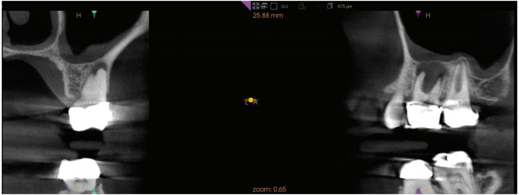
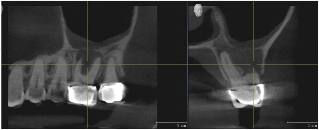
an intact maxillary sinus floor
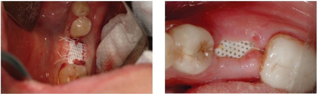
Tooth No. 14 was removed 2 weeks later. The patient was started on clindamycin 300 mg QID and chlorhexidine 0.12% oral rinse BID, both begun 2 days before surgery. There was a significant amount of fibrous and granulation tissue, which was sent for microscopic evaluation. This was thoroughly debrided and irrigated with sterile saline until only healthy bone remained in the extraction site. The bony sinus floor showed no perforations when examined clinically. The socket was packed with about 1.5 cc of mineralized and demineralized cortico-cancellous granules (Symbios® Allograft, Dentsply Sirona) until the bony defect was completely filled to the crest. This was covered by a 12 x 24 mm d-PTFE membrane (Symbios® OsteoShield®, Dentsply Sirona), which was trimmed to be 1 mm from each adjacent tooth and tucked between the buccal and lingual bone plates and a 5 mm deep full-thickness mucoperiosteal flap. This barrier was held in place with three PTFE sutures (Cytoplast™, Osteogenics) (Figure 3). The clindamycin was continued for 1 week and the chlorhexidine rinse for 2 weeks after the procedure. Sutures were removed after 2 weeks (Figure 4), and the barrier membrane was removed 6 weeks after surgery (Figure 5). Healthy granulation tissue was present under the membrane and fully epithelialized over the next 8 weeks.

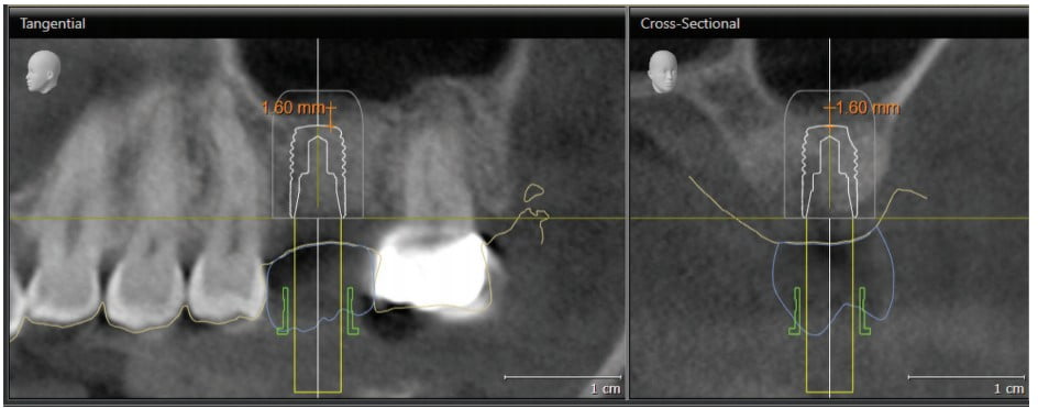
At 4 months’ post-extraction, the grafted extraction site was fully healed, and a periapical radiograph showed good bony volume preservation and adequate bone density for dental implant planning (Figure 6). A CBCT (GALILEOS, Dentsply Sirona) and CAD/CAM optical scan (CEREC Omnicam, Dentsply Sirona) were obtained to facilitate planning for fully guided implant surgery at the site of tooth No. 14. The optical image was used to create a digital wax-up (prosthetic proposal) estimating the size, shape, and position of the final restoration. This information was merged with the CBCT image in order to determine the optimal location, angulation, and depth of the implant fixture to be placed. Measurement of the alveolar ridge height on the CBCT image showed about 6.75 mm distance between the crest of the ridge and the bony sinus floor (Figure 7). The implant system chosen was the Astra Tech Implant System EV (Dentsply Sirona). The shortest wide diameter (4.8 mm) implant available in that system is 6 mm in height. The drills used for the System EV osteotomy are 1.0 mm longer than the implant fixture. Therefore, despite the successful ridge preservation graft, even with placing the shortest implant, the drills would most likely perforate the sinus floor and possibly the Schneiderian membrane as well. This situation necessitated bony augmentation of the floor of sinus above tooth No. 14 for a dental implant to be successfully placed.

Because the residual ridge height is greater than 5 mm and augmentation is necessary at only one implant site, an indirect (crestal) sinus lift was treatment planned. Traditional techniques use either two- or three-dimensional imaging to measure the residual ridge height, and the osteotomy is planned to stop about 1 mm short of the sinus floor. This is done using marked drills, osteotomes, or special rotary instruments to control the depth of penetration. This author has developed a simplified technique, taking advantage of CBCT-guided protocols for controlling the depth, angulation, and position of sequentially wider drills used to prepare the osteotomy. The sinus floor is up-fractured using either an osteotome or a piezo-surgery tip. The technique is applicable whether an open flap or tissue punch is used to expose the osteotomy site. An extensive search of the English language literature failed to find a similar method described.
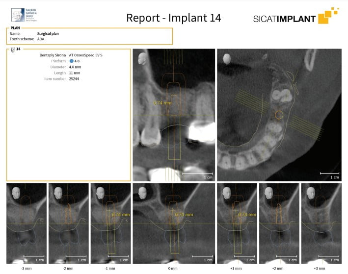
Using SICAT Implant software (SICAT GmbH, Bonn, Germany), an Astra Tech Implant System EV was planned with the ideal 4.8 mm diameter by 11 mm long straight implant with the occlusal end at bone level. The optical scan of the maxillary arch and the digital prosthetic proposal were loaded into the planning software and merged with the CBCT image. These images were used to fine-tune the position, angulation, and depth of this implant fixture (Figure 8). This plan is saved and called the “Surgical Plan,” and the planning report (Figure 9) is used to direct the surgical staff as to which implant system, size, and diameter will be used so that all necessary components are ready for surgery. In order to plan the crestal osteotomy to stop 0.5 mm – 1.0 mm inferior to the sinus floor, the implant length is shortened in the planning software so that the series of osteotomy drills will stop at the desired depth, keeping in mind that the drills will cut to 1 mm beyond the planned implant apex. In this case, a 6 mm long implant was selected and positioned so that the fixture apex is 1 mm – 2 mm below the sinus floor. The vertical position can be adjusted, but the implant position and angulation remain unchanged. (Figure 10). This treatment plan, the “Guide Plan,” is uploaded to the SICAT Portal for design of the surgical guide. This “tricks” the surgical guide designer in to thinking that a short implant will be placed without violation of the sinus floor. A stereolithographic (STL) file is available within 2 to 3 days if there are no issues, and this is used to print the surgical guide on a 3D printer (Form 3, Formlabs). The appropriate guide sleeve is then placed into the printed guide (Figure 11).


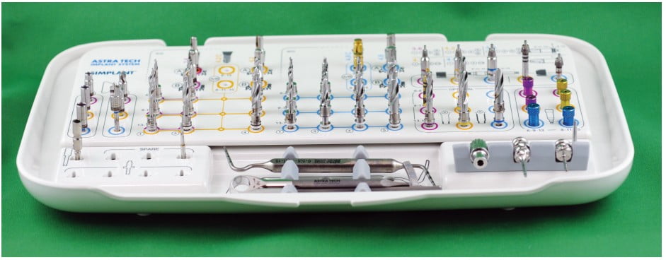
The patient presented for surgery the following week. Consent forms were reviewed, and the patient signed giving authorization for treatment. Approximately ½ cc of articaine HCl 4% with 1:100,000 epinephrine (Septodont USA) was infiltrated into the crest of the ridge at the tooth No. 14 site. There were adequate ridge volume and keratinized gingiva to use a flapless (tissue punch) approach.31 The surgical guide was placed, and following the “Guide Plan,” the AstraTech Implant System EV guided surgical kit (Figure 12) was used to prepare the osteotomy to the final diameter (4.5 mm) and approximately 0.6 mm below the left maxillary sinus floor. The surgical guide was removed, and a depth probe was used to verify that the sinus floor was intact. Approximately 0.2 cc of DBX putty demineralized bone matrix (MTF Biologics) (Figure 13) was placed into the osteotomy from a 1 cc syringe and pushed toward the sinus floor with an offset sinus floor elevation osteotome with a concave tip whose outer diameter was 4.2 mm. The bone putty acts as a cushion between the osteotome and the sinus floor and sinus membrane. Using light staccato contact with a surgical mallet, the bony sinus floor was up-fractured, and the Schneiderian membrane was lifted. The patient’s nasal bridge was stabilized to reduce the risk of post-procedural benign paroxysmal positional vertigo by dampening the vibration which can cause the otoconia in the inner ear from being dislodged and causing this complication.32,33,34 Once the sinus floor had been penetrated, the remainder of the contents of the bone putty syringe were injected through the osteotomy toward the sinus floor. The surgical guide was then replaced, and the 4.8 mm x 11 mm implant fixture was delivered to the osteotomy to the planned depth (“Surgical Plan”). The bone remaining in the osteotomy is pushed toward the sinus floor as the implant is advanced. The guide was then removed, the position and depth of the implant visually verified, and a 3.5 mm tall healing abutment (HealDesign™ EV, Dentsply Sirona) was placed to 15 Ncm of torque. A postoperative radiograph was taken to confirm the implant position and depth (Figure 14).
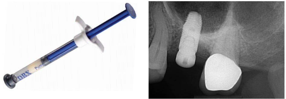
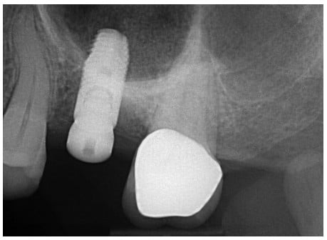
Healing was uneventful, and at 4 months’ post-placement, the implant was prosthetically restored. At the 6-month follow-up exam, the implant was stable without any signs of peri-implant disease. Radiographically, the bone level was unchanged from that at the time of placement. The implant apex was surrounded by bone (Figure 15).
Discussion
Since Summers first described the crestal sinus lift (Summers technique) in 1994,15 many clinicians have attempted to make the procedure more efficient and less likely to injure the delicate sinus membrane. There have also been many commercially available “crestal sinus lift” kits designed for this purpose. These kits are designed with either depth control attachments or marks, or drills with 1 mm incremental increase of length in order to control the depth of penetration of rotary instruments. These may not take into consideration the variable contour of the alveolar crest or the sinus floor, especially where there has been bony resorption.
The use of 3D CBCT imaging has significantly improved our diagnostic ability due to more accurate information.22 Implant planning software based on these images has improved our ability to compare variations of implant size and position in order to optimize our treatment results. Sinus lift techniques, whether performed via a crestal incision (indirect) or an open lateral wall (open) approach have allowed clinicians to place implants in atrophic posterior maxillae. The ideal candidate for an indirect (crestal) sinus lift needs only one or two adjacent posterior maxillary teeth to be replaced, has a concave sinus floor with surrounding walls,13 no bony septae near the edentulous space,9 and at least 5 mm of alveolar ridge height.14 Most of the techniques described use blunt- or concave-ended osteotomes, drills or other cutting instruments with stops to carefully approach the bony sinus floor to about 1 mm.19,23,24 If the alveolar ridge is irregularly shaped, or if the floor of the sinus is convexly curved, the selection of the correct-length instrument may be unclear.
A number of authors have reported using a CBCT-generated surgical guide to facilitate crestal sinus lift. In 2007, Drew, et al., used a surgical guide to direct tapered osteotomes, following the technique of Summers16 at the surgical site to up fracture the sinus floor.21 Attanasio, et al., described using a flapless, guided technique using a series of manual screw-tapered bone expanders to develop the osteotomy. The surgical guide was created by integrating information from a CBCT and intraoral optical scanner.29 Solano, et al., reported on a similar technique using a fully guided flapless crestal approach through a surgical stent designed by the merger of CAD/CAM and CBCT technology. The osteotomy was created using a specially designed surgical kit used for indirect sinus lift procedures only.30 All reported good results with simultaneous implant placement and emphasized the use of a surgical guide for accuracy and efficiency.
The technique reported here is unique in that it utilizes a prosthetically based treatment plan derived from the integration of CBCT, optical scanning, and state-of-the-art planning software to design a surgical guide that is used for preparation of the osteotomy using rotary instruments, followed by implant placement. The custom guide facilitates precision in the position, angulation, and depth of each drill. The drilling depth can be planned so that the distance from the tip of the drill to the sinus floor can be precisely controlled. The up-fracture of the sinus floor can then be completed by a single osteotome or using a piezosurgical device. This author has used piezosurgery (Piezotome® Cube, Acteon) over the past few years to reduce the risk of postoperative benign paroxysmal positional vertigo (BPPV) as a result of using a mallet against an osteotome to lift the bony sinus floor.32,33,34,35 When the osteotome method is used, an assistant places a thumb and forefinger over the bridge of the nose in order dampen the vibration from the mallet. This was found to be quite effective, and only one case of mild, self-limiting BPPV has been reported over the many years this technique has been used.
Conclusion
With this technique, no special drills, stops, or other devices are needed beyond the standard guided-surgery kit specific to the implant system being used. This author has performed this procedure on average 6 to 8 times per month over the past 10 years, with only 16 failures during the 4-month integration period. There is no significant learning curve to this protocol. Knowing the measurement of the drill length increment beyond the implant apex in the guided-surgery system being used is all that is necessary to plan the position of the “Guide Plan” fixture in the implant planning software so that the drills reach to 0.5 mm to 1.0 mm below the sinus floor. The clinician’s method of choice may be used to lift the sinus floor and graft under the Schneiderian membrane. This unique method is predictable, time-efficient, minimally invasive (especially if done flapless), comfortable for the patient, and has a high success rate.
CBCT is just one of the systems that Dr. Jay Reznick uses for increased efficiency in his practice. Read more about new opportunities for implant dentists in “Momentum for a new decade,” here:
https://implantpracticeus.com/momentum-for-a-new-decade/.
Author Info
 Jay Reznick, DMD, MD, is a Diplomate of the American Board of Oral and Maxillofacial Surgery. He received his undergraduate Biology degree from CAL-Berkeley, Dental degree from Tufts University, and his MD degree from the University of Southern California. He did his internship in General Surgery at Huntington Memorial Hospital in Pasadena and trained in Oral and Maxillofacial Surgery at L.A. County- USC Medical Center.
Dr. Reznick was one of the first North American adopters of fully guided, prosthetically based implant surgery and was the first specialist in the United States to integrate CBCT and CAD/CAM in his practice. He has taught dentists about basic and advanced implant dentistry, surgery, sleep apnea and snoring, and 3D digital technology for the past 2 decades. Dr. Reznick has published extensively in the dental and medical literature. He lectures frequently at dental meetings and educational conferences as well as giving live training courses to dentists from all over the world. Dr. Reznick is one of the Founders of the website OnlineOralSurgery.com, which educates practicing dentists in basic and advanced oral surgery techniques. He is also a consultant to a number of manufacturers and suppliers of dental and surgical instruments and equipment, and is on the Editorial Advisory Boards of a number of dental journals. Dr. Reznick is the Director of the Southern California Center for Oral and Facial Surgery in Tarzana, California. He can be reached at jay@onlineoralsurgery.com.
Disclosure: Dr. Reznick is a speaker and key opinion leader for Dentsply Sirona. He has no financial relationship with any of the companies mentioned in the article.
References
- Hansson S, Halldin A. Alveolar ridge resorption after tooth extraction: A consequence of a fundamental principle of bone physiology. J Dent Biomech. 2012;3.
- Wolff J. Das Gesetz der Transformation der Knochen. Berlin, Germany: August Hirschwald ;1892.
- Tan WL, Wong TLT, Wong MCM, Lang NP. A systematic review of post-extraction alveolar hard and soft tissue dimensional change in humans. Clin Oral Implants Res. 2012;23(suppl 5):1-21.
- Schropp L, Wenzel A, Kostopoulos L, Karring T. Bone healing and soft tissue contour changes following a single tooth extraction: a clinical and radiographic 12-month prospective study. Int J Periodontics Restorative Dent. 2003;23(4):313-323.
- Weng D, Stock V, Schliephake H. Are socket and ridge preservation techniques at the day of tooth extraction efficient in maintaining the tissues of the alveolar ridge? Systematic review, consensus statements, and recommendations of the first DGI Consensus Conference in September 2010, Aerzen, Germany. European J Oral Implantology. 2011;4:59-66.
- Mardas N, Trullenque-Eriksson A, MacBeth N, Petrie A, Donos N. Does ridge preservation following tooth extraction improve implant treatment outcomes: a systematic review: Group 4: therapeutic concepts and methods. Clin Oral Implants Res. 2015;26(suppl 11):180-201.
- Avila-Ortiz G, Elangovan S, Kramer KW, Blanchette D, Dawson DV. Effect of alveolar ridge preservation after tooth extraction: a systematic review and meta-analysis. J Dent Res. 2014;93(10):950-958.
- Sharan A, Madjar D. Maxillary sinus pneumatization following extractions: a radiographic study. Int J Oral Maxillofac Implants. 2008;23:1;48-56.
- Cavalcanti MC, Guirado TE, Sapata VM, et al. Maxillary sinus floor pneumatization an alveolar Ridge resorption after tooth loss: a cross-sectional study. Braz Oral Res. 2018;32(e64):1-10.
- Tasoullis G, Yao SG, Fine JB. The maxillary sinus: challenges and treatments for implant placement. Compend Contin Educ Dent. 2011;32(1):10-19.
- Tatum OH. Lecture presented to the Alabama Implant Congress. Clinical Implant Dentistry and Related Research. 1976.
- Boyne PJ, James RA. Grafting of the maxillary sinus floor with autogenous marrow and bone. J Oral Surg. 1980;38(8):613-616.
- Riben C, Thor A. The maxillary sinus membrane elevation procedure: augmentation of bone around dental implants without grafts — A review of a surgical technique. Int J Dent. 2012; 2012.
- Block MS. Improvements in the crestal osteotome approach have decreased the need for lateral window approach to augment the maxilla. J Oral Maxilofac Surg. 2016;74(11): 2169-2181.
- Rosen PS, Summers R, Mellado JR, et al. The bone-added osteotomes sinus floor elevation technique: multicenter retrospective report of consecutively treated patients. Int J Oral Maxillofac Implants. 1999;14(6)853-858.
- Summers RB. A new concept in maxillary implant surgery: the osteotome technique. 1994;15(2): 152-160.
- Pontes FSRAEF, Zuza EP, de Toledo BEC. Summers’ technique modification for sinus floor elevation using a connective tissue graft. A case report. J Int Acad Periodontol. 2010; 12(1):27-30.
- Koerner KR, Chong D. Simplified sinus lift surgery. Dent Today. 2013;32(12):56-60.
- Lin M. Controlled technique for indirect sinus grafting with simultaneous implant placement. Oral Health. 2013. https://www.oralhealthgroup.com/features/controlled-technique-for-indirect-sinus-grafting-with-simultaneous-implant-placement-mark-lin-bsc/. Accessed April 7, 2021.
- Cosci F, Luccioli M. A new sinus lift technique in conjunction with placement of 265 implants: A 6-year retrospective study. Implant Dent. 2000;9(4):363-368.
- Bernadello F, Righi D, Cosci F, et al. Crestal sinus lift with sequential drills and simultaneous implant placement in sights with < 5 millimeters of native bone: a multicenter retrospective study. Implant Dent. 2011;20(6):439-444.
- Tyndall DA, Price JB, Tetradis S, Ganz SD, Hildebolt C, Scarfe WC. Position statement of the American Academy of Oral and Maxillofacial Radiology on selection criteria for the use of radiology in dental implantology with emphasis on cone beam computed tomography. Oral Surg Oral Med Oral Pathol Oral Radiol. 2012;113(6):817–826.
- Drew HJ, Chiang T, Simon BI. The osteotome technique: modifications to the original approach. Inside Dentistry. 2007;3(10):58-65.
- Checci L, Felice P, Antonini ES, et al. Crestal sinus left for implant rehabilitation: a randomized clinical trial comparing the Cosci and the Summers techniques. A preliminary report on the complications and patient preference. Eur J Oral Implantol. 2010;3(3):221-232.
- Thomas TJ, Bindra AS. Internal sinus membrane elevation in patients with less than 5 millimeters residual bone height. Compend Contin Educ Dent. 2018;39(5):e13-e16.
- Abadzhiev M. Alternative sinus lift techniques – literature review. Journal of IMAB Annual – Proceeding (Scientific Papers), Book 2. 2009;23-27.
- Troedham A, Kurrek A, Wainwright M, et al. The transcrestal hydrodynamic ultrasonic cavitational sinus lift: results of a two-year prospective multicenter study on 404 patients, 446 sinus lift sites and 637 inserted implants. Open J Stomatol. 2013;3:471-484.
- Troedham A, Kurrek A, Wainwright M, Jank S. Schneiderian membrane detachment using transcrestal hydrodynamic ultrasonic cavitational sinus lift: a human cadaver head study and histologic analysis. J Oral Maxillofac Surg. 2014;72(8): 1503.e1-1503.e10.
- Chasioti E, Sayed M, Drew H. Novel techniques with the aid of a staged CBCT guided surgical protocol. Case Rep Dent. 2015;2015.
- Attanasio F, Bortolini S, Carbone D, Pacifici A. Flapless cone beam computed tomography — guided implant surgery with contextual transcrestal sinus lift augmentation using new bone compactor tools. Case Rep Dent. 2020;2020.
- Solano N, Ortega A, Gutiérrez P, Ortega A, et al. Use of a surgical guide for flapless transcrestal maxillary sinus floor elevation and immediate placement of dental implant: a case report. Res Rep Oral Maxillofac Surg. 2020;4(1):033.
- Greenstein G, Cavallero S. The clinical significance of keratinized gingiva around dental implants. Compendium of Contin Educ Dent. 2011;32(8):24-31.
- Ackay H, Ulu M, Kelebek S, Aladag I. Benign paroxysmal positional vertigo following sinus floor elevation in a patient with antecedents of vertigo. J Maxillofac Oral Surg. 2016;15:(suppl 2):351-354.
- Peñarrocha M, Garcia A. benign paroxysmal positional vertigo as a complication of interventions with osteotome and mallett. J Oral Maxillofac Surg. 2006;64(8) 1324.
- Saker M, Ogle O. Benign paroxysmal positional vertigo subsequent to sinus lift via closed technique. J Oral Maxillofac Surg. 2005;63(9):1385-1387.
Stay Relevant With Implant Practice US
Join our email list for CE courses and webinars, articles and mores