Dr. Michael D. Scherer summarizes a contemporary approach using simple techniques to enhance visualization of restoration contour, separating soft tissues with simple techniques, and proposes that radiographic guides may no longer be necessary for implant overdenture therapy
Synopsis/Abstract
Treatment planning for implant overdentures can be challenging because of the interplay between bone volumes, angulation, and denture base contour requirements.Narrow-diameter overdenture implants, while having an easy and predictable surgical protocol, often are placed without regard to restorative goals because of the difficulty and added expense of fabricating a radiographic guide. Simple techniques are available to enhance visualization of complete dentures during cone-beam computed tomography (CBCT) imaging. This article aims to illustrate the use of soft tissue separation techniques and assessment of CBCT scans for narrow-diameter overdenture implants.
Introduction
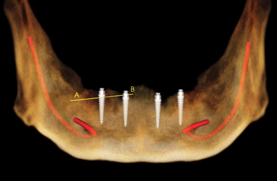
Radiographic visualization of the alveolar ridge bone volume, current tooth position, and the definitive restorative plan are necessary steps in the treatment sequence and planning of implant positions and final restoration contours. Proper positioning of the narrow-diameter implant body is critical to the success of the surgical procedure, initial and definitive prosthetics, and long-term maintenance of both the implant and restoration. The implant position not only is dependent upon location of sufficient bone volume, but also must satisfy esthetic, biomechanical, and functional requirements. While narrow-diameter implants, such as the ZEST LOCATOR® Overdenture Implant System (LODI), offer flexible and predictable surgical placement protocols, many clinicians often plan implant positions solely based upon radiographic appearance of bone volumes with the assumption that the surgical procedure is the prime directive of implant therapy. Critical to treatment planning procedures, it requires a thorough evaluation of the current or proposed restoration space.
Proper evaluation of three-dimensional restorative space is essential during treatment evaluation for implant restorations. This restorative space is bound by the proposed occlusal plane, denture-bearing tissues of the edentulous ridge, and oro-facial tissues.1 The space is also controlled by the patient’s neutral zone, which is the region balanced by the inward force of lips and cheeks and that of the outward force of the tongue.2 Proper control of this balance is largely dependent upon the buccolingual position of the teeth and denture base contour.3 Inadequate attention to analyzing the restorative space may lead to problems such as an over-contoured prosthesis, compromise in the neutral zone, fractured teeth and/or denture bases, artificially opened occlusal vertical dimension, and the need to perform additional surgical procedures.4-6
The purpose of this article is to outline essential steps and techniques involved in proper radiographic assessment of sites for narrow-diameter overdenture implants to avoid potential treatment planning complications. Additionally, this article aims to describe contemporary 3D imaging using soft tissue separation techniques to visualize restorative plans without having to utilize a radiographic guide.
Case report: inadequate restoration treatment planningfor overdenture implants
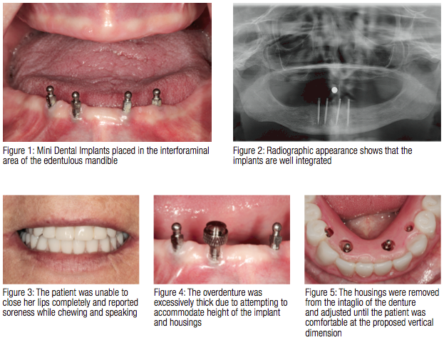
Patients who are treated without regard to restorative space have difficulty with adapting to the bulkiness of their restoration. An example of a patient seen by this author is shown in Figures 1-5. This patient had four 3M ESPE Mini Dental Implants (MDI), (3M, St. Paul, Minnesota) placed approximately 5 years prior to presenting to the author for evaluation (Figures 1 and 2). The patient expressed no pain or dysfunction with her implants; however, she hasn’t been able to wear her mandibular denture since the implants were placed. She expressed concerns that she was unable to speak effectively and felt strained with both dentures in her mouth (Figure 3). Frustrated, she decided to leave her denture out of her mouth and has accommodated to not wearing the denture. Diagnostic procedures were completed, and a clinical assessment showed that her vertical dimension was opened beyond her comfort level. This was a result of the previous clinician attempting to accommodate the height of the tall implants, housings, and acrylic resin within the denture borders (Figure 4). The housings were removed, the denture adjusted until her vertical dimension was adequate, and the determination was that she had to have the implants removed (Figure 5). Unfortunately, lack of restorative assessment, lack of effective radiographic visualization, and insufficient attention to fundamentals of complete denture fabrication resulted in an outcome that was less than optimal.
CBCT scanning and implant treatment planning
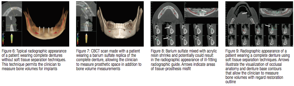
The use of cone-beam computerized tomography (CBCT) has gained popularity as it allows for three-dimensional evaluation as opposed to traditional two-dimensional radiographic techniques. CBCT allows proper visualization of critical anatomical structures and provides a superior amount of information.7-9 CBCT software packages also allow for interpretation of Digital Imaging and Communications in Medicine (DICOM) files via volumetric or surface rendering technology. Figure 6 illustrates a CBCT scan of a patient wearing complete dentures without the use of a radiographic template. While the volume, width, and height of bone can be properly determined for position of a narrow-diameter implant (LODI, ZEST Anchors, Escondido, California) within the bone, it is not possible to fully identify the proper implant position relative to the planned restorative goal. Various methods of radiographic visualization methods have been described in the literature with many reports and techniques described involving duplicating the existing or proposed restoration and fabricating a radiographic guide.10-16 Radiographic guides can reliably act as tooth or restoration outline markers indicating incisal edge position, buccolingual position aides, and denture base contour (Figure 7). Additionally, these markers may potentially act as a fiducial marker allowing for accurate representation of the final restorative goals by ensuring adequate radiographic determination for narrow-diameter implant placement. By using these as a template for planning, critical anatomical features are identified, and dental implants may be digitally planned.
Traditional radiographic visualization for fully edentulous patients typically involves the use of duplicating the patient’s existing complete denture and fabricating a barium sulfate and acrylic resin replica of various radiodensities.11,13,15,16 The method of duplication most likely calls for the use of an irreversible hydrocolloid (alginate) or a polyvinylsiloxane (PVS) impression. It requires laboratory components, and generally requires two clinical appointments. While visualization can be achieved with this approach, some practitioners choose not to fabricate radiographic guides because of the extra steps and costs involved. Laboratories typically charge between $50–$200 for fabrication of a radiographic guide in addition to approximately $50 worth of impression material used, dental gypsum, and packing material needed to ship the duplicate index of the patient’s denture. As mentioned, a second clinical appointment is necessary to fit the prosthesis prior to the
CBCT scan. Even after guide fabrication and adjustments in the mouth, as well as considering that acrylic resin has a shrinkage of up to 21%, there is a possibility of the radiographic guide not adequately fitting the soft tissues.18 Prosthetic space, angulation, and height adjustments in relation to bone volumes are possible with the addition of barium sulfate. Figure 8 illustrates a CBCT scan of a patient wearing an ill-fitting barium sulfate/acrylic resin radiographic guide. This method allows for the clinician to visualize the restorative contours in addition to the bone vol-ume measurements previously depicted, however, due to the aforementioned, can be a challenging method of radiographic visualization. Clinical procedures that reduce cost and complexity, yet still allow for achieving an appropriate clinical outcome, are always of interest to private practitioners. It is the opinion of the author that with the current cone-beam software packages in conjunction with digital technology, distinct radiographic templates are rapidly becoming unnecessary.
Case report: soft tissue separation techniques for narrow-diameter overdenture implants
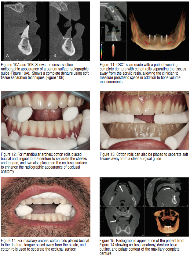
Air space on a CBCT image is represented by dark space, and the patient volume is represented by shades of grey to bright white points. The Hounsfield unit (HU) scale is a relative measurement of the radiodensity of an object within a CT scan, indirectly providing amounts of gray within an image. Radiodensity of cortical bone (1700 HU) allows it be easily visible on CBCT radiographs as compared to air (-1000 HU) and tissues (50 HU).19 Typical radiographic techniques do not permit visualization of soft tissue contours separate from acrylic denture resin. The comparison of tissue radiodensity and that of acrylic denture resin (70 HU) makes it more difficult to discern the differences between the two.19 Figure 9 illustrates a CBCT radiograph of a mandibular complete denture with soft tissue and occlusal separation. Looking at this radiographic representation of the denture contour, it is easy to see all of the major factors related to essential treatment planning: tooth position, denture base contour, and occlusal morphology. Comparing the radiographic appearance of the barium sulfate replicate of the complete denture to that of just the complete denture reveals a similar appearance (Figures 10A and 10B). Narrow-diameter implant overdenture (LODI, ZEST Anchors, Escondido, California) treatment planning with measurement-based CBCT analysis is facilitated with this simple yet intuitive approach for fully edentulous patients (Figure 11).
Separation of soft tissues during CBCT scans is a very simple technique that creates negative air space, which contrasts with objects that are not radiopaque, such as acrylic resin. Multiple methods have been employed by this author; however, the simplest and most readily available technique is to place a combination of cotton rolls around the denture prior to the CBCT scan. In most mandibular narrow-diameter overdenture implant cases where the patient is wearing a complete denture, seven cotton rolls are placed: two on the lingual, two on the occlusal, and three in the buccal vestibule (Figure 12). The lingual cotton rolls are used to keep the tongue away from the lingual slope of the complete denture; the occlusal cotton rolls permit visualization of the occlusal surface details; and the buccal cotton rolls keep the cheeks and lips away from the denture surface. If the clinician wishes to have a duplicate denture made for the purposes of a surgical guide, cotton rolls can also be applied in a similar fashion around a clear surgical template (Figure 13). Alternatively, a single extended length cotton roll can take the place of multiple individual cotton rolls.

For maxillary narrow-diameter over-denture implant cases where the patient is wearing a complete denture, five cotton rolls are placed: two on the occlusal and three in the buccal vestibule (Figure 14). During the CBCT scan, the patient is instructed to keep the tongue away from the palate. By employing these techniques, dark areas corresponding to air space are created on the CBCT volume-enhanced visualization of the occlusal surfaces of denture teeth, tongue anatomy, and palate (Figure 15). With some CBCT software packages (Invivo, Anatomage, San Jose, California), special rendering modes will permit visualization of bone volume and the complete denture without secondary CBCT scans or complicated techniques (Figure 16).
Based upon these simple techniques, the clinician can easily visualize restoration plans in relation to bone volumes in 3D. Angulation, depth, and position of implants can be modified based upon this visualization, which greatly enhanced treatment planning for narrow diameter overdenture implants. The virtual treatment plan allows for fabrication of a 3D-printed model and a computerized guide (Anatomage Guide, Anatomage, San Jose, California) with special metal sleeve inserts that permit placement using implant osteotomy drills (Figure 17). After ensuring complete adaptation of the surgical guide to the alveolar ridge, anchor pins assist in stabilizing the surgical guide during implant osteotomy preparation. Implants are placed with precision through the surgical guide,
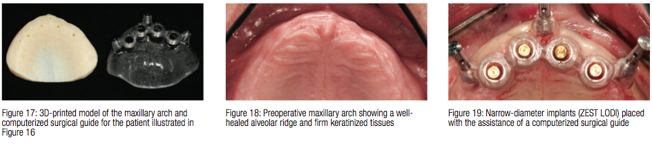
and LOCATOR Implant abutments are attached to the implants (Figures 18-19). Using the computerized guide to place narrow-diameter implants allows the clinician to precisely place the implants, to minimize surgical trauma, and to ensure that the preoperative virtual plan is transferred from the computer screen to the surgical procedure (Figure 20).

Conclusion
Proper visualization of bone volumes and restorative plans for narrow-diameter overdenture implants is critical and requires careful preoperative assessments. While narrow-diameter overdenture implants, such as the ZEST Anchors LODI System, are an excellent treatment option for patients with narrow ridges because of the flexible surgical placement protocol, it is critical to properly plan implant placement around restorative goals. Visualization of bone volume and restorative plans is facilitated with CBCT imaging and simple techniques using cotton rolls to separate soft tissues and enhance the visualization of a complete denture. While barium sulfate and other radiopaque materials may still have a place in implant dentistry, it is the opinion of this author that use of these materials is no longer necessary for restorative visualization and treatment planning for narrow-diameter overdenture implants.
- Ahuja S, Cagna DR. Classification and management of restorative space in edentulous implant overdenture patients. JProsthetDent. 2011;105(5):332-337.
- Beresin VE, Schiesser FJ. The neutral zone in complete dentures.JProsthetDent. 1976;36(4):356-365.
- Cagna DR, Massad JJ, Schiesser FJ. The neutral zone revisited: from historical concepts to modern application. JProsthetDent. 2009;101(6):405-412.
- Lee CK, Agar JR. Surgical and prosthetic planning for a two-implant-retained mandibular overdenture: a clinical report. JProsthetDent. 2006;95(2):102-105.
- Bidra AS. Consequences of insufficient treatment planning for flapless implant surgery for a mandibular overdenture: a clinical report. JProsthetDent. 2011;105(5):286-291.
- Porwal A, Sasaki K. Current status of the neutral zone: a literature review. JProsthetDent. 2013;109(2):129-134.
- White SC, Heslop EW, Hollender LG, Mosier KM, Ruprecht A, Shrout MK. Parameters of radiologic care: An official report of the American Academy of Oral and Maxillofacial Radiology. OralSurgOralMedOralPatholOralRadiolEndod. 2001;91(5):498-511.
- Benavides E, Rios HF, Ganz SD, An CH, Resnik R, Reardon GT, Feldman SJ, Mah JK, Hatcher D, Kim MJ, Sohn DS, Palti A, Perel ML, Judy KW, Misch CE, Wang HL. Use of cone beam computed tomography in implant dentistry: the International Congress of Oral Implantologists consensus report. ImplantDent. 2012;21(2):78-86.
- Dreiseidler T, Mischkowski RA, Neugebauer J, Ritter L, Zöller JE. Comparison of cone-beam imaging with orthopantomography and computerized tomography for assessment in presurgical implant dentistry. IntJOralMaxillofacImplants. 2009;24(2):216-225.
- Engelman MJ, Sorensen JA, Moy P. Optimum placement of osseointegrated implants. JProsthetDent. 1988;59(4):467-473.
- Israelson H, Plemons JM, Watkins P, Sory C. Barium-coated surgical stents and computer-assisted tomography in the preoperative assessment of dental implant patients. IntJPeriodonticsRestorativeDent. 1992;12(1):52-61.
- Pesun IJ, Gardner FM. Fabrication of a guide for radiographic evaluation and surgical placement of implants. JProsthetDent. 1995;73(6):548-552.
- Basten CH, Kois JC. The use of barium sulfate for implant templates.JProsthetDent. 1996;76(4):451-454.
- Takeshita F, Tokoshima T, Suetsugu T. A stent for presurgical evaluation of implant placement. JProsthetDent. 1997;77(1):36-38.
- Kopp KC, Koslow AH, Abdo OS. Predictable implant placement with a diagnostic/surgical template and advanced radiographic imaging. JProsthetDent. 2003;89(6):611-615.
- Oh WS, Saglik B. A simple method to duplicate a denture for an implant surgical guide. JProsthetDent. 2008;99(4):326-327.
- Mecall RA, Rosenfeld AL. The influence of residual ridge resorption patterns on implant fixture placement and tooth position. 2. Presurgical determination of prosthesis type and design.IntJPeriodonticsRestorativeDent. 1992;12(1):32-51.
- Mojon P, Oberholzer JP, Meyer JM, Belser UC. Polymerization shrinkage of index and pattern acrylic resins. JProsthetDent. 1990;64(6):684-688.
- Mah P, Reeves TE, McDavid WD. Deriving Hounsfield units using grey levels in cone beam computed tomography. DentomaxillofacRadiol. 2010;39(6):323-335.
Stay Relevant With Implant Practice US
Join our email list for CE courses and webinars, articles and mores
