Educational aims and objectives
This clinical article aims to present an overview of CBCT technology and suggest guidelines to follow when incorporating it into an implant practice.
Expected outcomes
Implant Practice US subscribers can answer the CE questions by taking the quiz to earn 2 hours of CE from reading this article. Correctly answering the questions will demonstrate the reader can:
- Identify the basic elements of CBCT hardware, the fundamental principles of the associated workflow, and the practical benefits and limitations of this technology.
- Identify the characteristics of the X-ray source in a CBCT unit.
- Identify various types of CBCT units available in dentistry.
- Realize the steps in the workflow of image capture.
- Define the Ray-sum technique.
- Recognize some limitations of CBCT.
- Realize some benefits of implementing CBCT.
Dr. Johan Hartshorne’s in depth look at CBCT in implant treatment shows the many aspects of this imaging modality that must be considered before implementation.
Dr. Johan Hartshorne highlights technical aspects practitioners need to consider before adding a cone beam computed tomography unit to their practice
The development of inexpensive X-ray tubes, high-quality detector systems, and powerful personal computers has paved the way for commercially available and affordable 3D cone beam computed tomography (CBCT) imaging systems for dental practices.
This article is the first of a series providing clinicians with an overview of technical considerations relating to basic elements of CBCT hardware, types and characteristics of different CBCT units, the fundamental principles of the CBCT imaging workflow chain, and the benefits and limitations of incorporating a CBCT unit into your practice. It also aims to provide some guidelines and recommendations on what factors must be considered when purchasing a CBCT unit.
These technical considerations are intended to enhance the practitioner’s understanding of the fundamental principles required for safe and effective use of this technology. CBCT technology is increasingly being introduced into the dental practice setting due to its invaluable diagnostic and communication capabilities, high quality and accurate images, ease of use, and suitability.
Introduction
Intraoral and extraoral 2D radiographic imaging procedure (periapical, lateral cephalometric, and panoramic), traditionally used for preoperative dental implant diagnostics and treatment planning, suffer from the same inherent limitations common to all planar 2D projections — namely, magnification, distortion, superimposition, and misrepresentation of structures (Scarfe and Farman, 2008).
Although numerous efforts have been made toward developing 3D radiographic imaging — such as stereoscopy, tuned aperture computed tomography, and multidetector computed tomography (MDCT) — the use of these advanced CT imaging techniques has been unavailable or limited for most dental practitioners because of cost, physical complexity and size, and high-radiation dose considerations (Scarfe and Farman, 2008).
The development of inexpensive X-ray tubes, high-quality detector systems, and powerful PCs has paved the way for commercially available and affordable 3D CBCT imaging systems, small enough to be used in dental practice (Scarfe et al, 2006).

Since its introduction for the maxillofacial region by Italian co-inventors Attilio Tacconi and Piero Mozzo in 1998, CBCT imaging has become an important and established diagnostic tool for the clinical assessment and treatment planning of patients needing dental implants (Sato, et al., 2004; Kobayashi, et al., 2004; Hatcher, et al., 2003). The value of CBCT imaging as a diagnostic tool has also been reported for various other fields of dentistry, such as oral-maxillofacial surgery, dental traumatology, endodontics, temporo-mandibular joint, periodontology, orthodontics, and forensic odontology (Scarfe and Farman, 2008; Alamri, et al., 2012).
The widespread use of CBCT scanners, however, has resulted in several concerns for clinicians regarding:
- Indications, justification, and optimization of CBCT exposures
- Training to optimize safe and effective use of CBCT in the clinical setting
- Quality assurance of CBCT scanners
It is, therefore, important for clinicians to have a full understanding of the technical principles of dental CBCT imaging to purchase the correct machine, and using it correctly and effectively to reap the full benefit, while minimizing radiation-related patient risk (Schulze, et al., 2011).
CBCT imaging hardware
CBCT imaging hardware consists of three basic elements:
- X-ray source (X-ray generator)
- Image detector (sensor)
- Gantry (C-arm or rotating platform) that connects the X-ray source and the detector (Figure 1).

X-ray source
An X-ray beam is generated in a tube containing an electrical circuit with two oppositely charged electrodes (such as cathode and anode) separated by a vacuum (Figure 2). The cathode is composed of a filament that gets heated when an electric current is applied, inducing the release of electrons through thermionic emission.
Because of the high voltage between the cathode and anode, these released electrons will be accelerated toward the anode, colliding with it at high speeds at a location called the focal spot. Ideally, this focal spot is point-sized, but typical focal spots in CBCT are 0.5 mm wide; the size of the focal spot is one of the determinants of image sharpness (Pauwels, et al., 2015). The energy generated through this collision is mainly lost as heat, but a small part is converted into X-rays through bremsstrahlung. (Editor’s note: According to the Merriam-Webster dictionary, bremsstrahlung is “the electromagnetic radiation produced by the sudden deceleration of a charged particle in an intense electric field (as of an atomic nucleus).”
X-rays are emitted in all directions, but absorption within the anode and the tube housing results in a beam emerging from the tube perpendicular to the electron beam. The anode surface is slightly tilted to maximize the outgoing X-ray beam through the exit window of the tube (Pauwels, et al., 2015). A lead alloy collimator is used to block X-rays not passing through the scanned volume or region of interest (ROI), thus reducing patient exposure.

Most CBCT systems have multiple, pre-defined field-of-view (FOV) sizes, so a collimator will have several pre-defined openings according to the FOV sizes (Pauwels, et al., 2015); thus, collimation of the X-ray beam by adjustment of the FOV limits the radiation to the ROI only. Furthermore, collimation defines the width and height of the primary X-ray beam, and size of the reconstructed FOV.
The cone-shaped X-ray beam has two primary characteristics: quality and quantity. Quality refers to the overall energy of the photons in the X-ray beam. Factors that affect (increase or decrease) X-ray beam quality are peak kilo voltage (kVp), filtration, and the type of waveform used. Quantity refers to the number of photons in the X-ray beam. When the number of photons increases, beam intensity increases, affecting X-ray beam quantity. This is affected by change in tube anode current (mAs), kVp, filtration, and changes in distance from the tube.
Beam hardening refers to the process in which the quality (energy) of an X-ray beam is increased by removing lower energy photons with appropriate filtration. Exposure can be controlled either automatic or manual adjustment of kVp or mAs.

Image detector
X-ray detectors convert the incoming X-ray photons to an electrical signal and are a crucial component of the imaging chain (Figure 3). There are two types image detectors (also referred to as “sensors”) used in contemporary CBCT units: either a charge-coupled device with a fiber-optic image intensifier detector or an amorphous silicon flat-panel detector. During the initial introduction of CBCT, most units were constructed with the large, bulky image-intensifier detectors.
Most CBCT scanners have nearly all transitioned to the smaller, flat panel linear array detectors (Abromovitch and Rice, 2014). Besides being less bulky and having a smaller footprint, the flat panels have minimal distortion of the image dimensions at the periphery of an image display, a higher dose efficiency, a wider dynamic range, and can be produced with either a smaller or larger FOV8; hence, these units are considered to generate better data volume sets.
Gantry
Most dental CBCT systems have a fixed C-shaped rotating platform or gantry with the X-ray source and the image detector mounted on opposite sides of the C-arm or gantry (Figure 4). During a CBCT scan, the C-arm or gantry performs a partial (180°) or full rotation (360°), in which the X-ray source and reciprocating area detector synchronously move around the patient’s head (Figure 4).
Some CBCT devices offer the opportunity to select a partial rotation with a reduction of radiation dose to the patient (Pauwels, et al., 2015). The patient’s head is stabilized during the rotation process with a head restraint device, while capturing multiple 2D images at different intervals, also known as “basis” images of the FOV. These series of basis images are referred to as projection data or data volume (Pauwels, et al., 2015). The head restraint mechanism (Figure 5) is used to minimize movement and to limit motion artifacts during the 3D scanning process (Scarfe and Farman, 2008).

Types of CBCT machine
There are several different dental CBCT machines that vary in their design, footprint, detector configurations, and protocol selection features. CBCT machines can be categorized according to orientation of the patient during image acquisition (Figure 6) and the scan volume, also referred to as FOV-irradiated (Scarfe and Farman, 2008) (Figure 7).
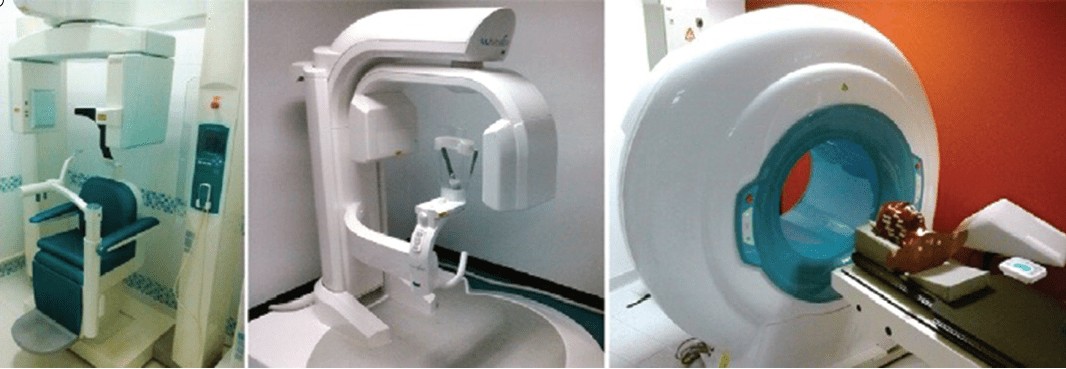
Patient orientation

There are three types of CBCT gantries that can scan patients in different positions (Figure 6): seated, standing, and supine. Each has advantages and disadvantages. Scanners allowing for standing patient positioning are usually more accommodating for wheelchairs (Figure 8) and occupy no more space than a panoramic radiography device. However, some standing units may not be able to be adjusted to a height to accommodate wheelchair-bound patients.
Seated units, on the other hand, are more comfortable. However, fixed seats may not allow scanning of physically disabled or wheelchair-bound patients. Additionally, scanners with a built-in chair or table occupy a larger space. CBCT scanners that require the patient to lie supine occupy a larger surface area and may not be accessible for patients with physical disabilities.
Scan volume or field of view
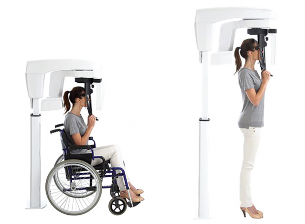
more accommodating for wheelchairs
CBCT machines can also be categorized according to the available FOV or selected scan volume height as follows (Figure 7):
- Localized region: approximately 5 cm or less (such as dentoalveolar and temporo-mandibular joint)
- Single arch: 5 cm to 10 cm (such as maxilla or mandible)
- Interarch: 7 cm to 10 cm (such as mandible and superiorly to include the inferior concha)
- Maxillofacial: 10 cm to 15 cm (such as mandible and extending to Nasion)
- Craniofacial: greater than 15 cm (such as from the lower border of the mandible to the vertex of the head).
The FOV is an important parameter that defines a CBCT imaging protocol. It represents collimation of the beam size to a pre-determined area. Adjusting the FOV determines the size of anatomic coverage, image resolution, and patient radiation dose. In general, clinicians should select the smallest FOV that provides adequate anatomic coverage and adequate image resolution (www.sedentexct.eu/files/radiation_protection_172.pdf). For most units, a smaller FOV is acquired using a smaller voxel size and thus has higher spatial resolution.
Additionally, the reduced scatter radiation with a smaller FOV also contributes to improved image quality. Typically, the radiation dose decreases with a smaller FOV size (Mallya, 2015). FOV limits depend on the detector size and shape, beam projection geometry, and the ability to collimate or not. It is desirable to limit the FOV to the smallest volume that can accommodate the ROI.

Image workflow: 3D CBCT scanner
CBCT image production workflow consists of four stages:
- Acquisition
- Detection
- Reconstruction
- Display of the image (Scarfe and Farman, 2008) (Figure 9)
Acquiring the scan
Depending on the type of cone beam imaging system used, the subject may be positioned in a standing, sitting, or supine position, with the head or area of interest placed at the center of the CBCT system. After situating the patient, the head is stabilized with a restraint mechanism and chin rest to minimize movement during scanning. The frame rate, speed of rotation, FOV, and completeness of the trajectory arc are set manually or automatically to get the image desired.
The X-ray source produces a cone-shaped beam of ionizing radiation that passes through the center of the ROI in the patients’ head to the X-ray detector on the other side. A single partial or full rotational scan from the X-ray source takes place, while the reciprocating detector moves synchronously with the scan around a fixed fulcrum within the ROI (Scarfe and Farman, 2008).
This fulcrum acts as the center of the final acquired volume imaged. During the scan rotation, each projection image is made by sequential image capture of the attenuated X-ray beam by the detector. While rotating, the X-ray source emits radiation in a continuous or pulsed mode, allowing 2D projection radiographs or basis images (Scarfe and Farman, 2008). In a single rotation, the detector can generate between 150 to 600 high-resolution 2D basis images (Pauwels, et al., 2015). The series of basis images are referred to as projection data. Typical rotation times range between 10 and 40, although faster and slower scan protocols exist.
Technically, the easiest method of exposing the patient is to use a continuous beam of radiation during the scan rotation and allow the X-ray detector to sample or capture single images of the attenuated X-ray beam in its trajectory. However, continuous radiation emission does not contribute to the formation of the image and results in greater radiation exposure to the patient (Abromovitch and Rice, 2014).
In most contemporary units, the X-ray beam exposure is pulsed to coincide with the detector sampling. Pulsed X-ray beam exposure at intervals allows time between basis image acquisition for the signal to be transmitted from the detector area to the data storage area and the detector to rotate to the next site or angle of exposure. Hence, the X-ray tube does not generate X-rays for the entire rotational cycle, meaning radiation exposure time is markedly less than scanning time (Abromovitch and Rice, 2014).
The total scan time is equivalent to exposure time, where the X-ray tube allows only continuous exposure. In comparison, for CBCT scanners using pulsed exposure, the exposure time is markedly less than scan time; thus, pulsed X-ray beam generation is preferable as it results in less radiation dosage to the patient. Pulsed X-ray beam exposure is a major reason for considerable variation in reported cone-beam unit dosimetry (Scarfe and Farman, 2008).
Depending on the mAs, a 180° rotation protocol can lead to a slight or more pronounced increase in noise than in a 360° protocol. A partial rotation and reduced sampling associated with shorter scan time tends to decrease overall image quality due to the amount of noise associated with reduced mAs (Pauwels, et al., 2015).
More projection data from a 360° rotation protocol provides more information to reconstruct the image; allowing for greater spatial and contrast resolution; increasing the signal-to-noise ratio, producing “smoother” images; and reducing metallic artifacts. However, more projection data usually necessitate a longer scan time, a higher patient dose, and longer primary reconstruction time. In accordance with the “as low as reasonably achievable” (ALARA) principle, the number of basis images should be minimized to produce an image of diagnostic quality (Scarfe and Farman, 2008).
Detecting the image

During scan rotation, a divergent pyramidal or cone-shaped source of ionizing radiation is directed through the middle of the ROI (fulcrum), and the transmitted attenuated radiation is projected onto the detector on the opposite side (Figure 4). The X-ray source emits X-ray photons. The scintillator in the detector absorbs the X-ray photons and converts them into light. The photodiode array in the amorphous silicon panel absorbs the light and converts it into an electronic charge (Pauwels, et al., 2015).
Each photodiode represents a pixel or 2D picture element (Figure 10). The electronic charge at each pixel is read out by low-noise electronics to provide digital data. This data is transmitted to, and collected at, a dedicated computer.
The pixel size of the detector is the principle determinant of the voxel size (3D picture element) (Figure 10). Detectors with small pixel size capture fewer X-ray photons per voxel and result in more noise. In CBCT, pixel size can vary from 0.12 mm to 0.4 mm. The lower pixel-size image takes more exposure time (20 to 40 seconds) and more radiation.
It is very susceptible to movement distortion. Thus, even though small pixel-size images lend more definition to smaller object areas, the risk of movement distortion makes it impractical for most applications. Therefore, imaging subtle pathology, such as caries, root fractures, or periodontal bone loss, is not practical due to movement-related distortion.
Reconstructing the image
In a single rotation, the detector can generate anywhere between 150 to 600 high-resolution 2D basis images. The basis images, each with more than one million pixels with 12 to 16 bits of data assigned to each pixel, is transferred to a processing computer for reconstruction using software programs incorporating sophisticated algorithms, including back filtered projection to construct a 3D image, also known as a volumetric data set (Scarfe, et al., 2006).
The most widespread form of 3D-filtered back projection in CBCT uses the Feldkamp-Davis-Kress algorithm (Pauwels, et al., 2015). Reconstruction time is usually less than 3 minutes for standard resolution scans (Scarfe and Farman, 2008) and is dependent on the quality of the software and computer hardware. Once the basis images are reconstructed, they can be recombined into a single digital 3D image or volumetric data set for visualization by the clinician.
The voxel is the smallest individual volume element in the 3D environment and determines the spatial resolution of the image (Figure 10). They are cubic in nature and equal in all dimensions (isotropic). When viewed as a digital image, the pixel size controls the resolution. The smaller pixel size yields a higher resolution image and, conversely, the larger the pixel size, the lower the resolution or quality of the image.

Displaying and manipulating the image
CBCT technology provides a complete digital model at the end of the process. The software also provides the clinician with a relatively large choice of display formats, allowing for 2D, 3D, and panoramic views of the mouth and head, along with other viewing options to help focus on areas of interest.
The default presentation of the 3D volumetric data set is a compilation of all available voxels presented to the clinician in real time on screen, as secondary reconstructed 2D cross-sectional images in three orthogonal planes (axial, sagittal, and coronal) for visualization and manipulation (Figure 11).
Axial planes are a series of slices from top to bottom in the volume. Sagittal planes are a series of 2D slices from left to right, and coronal planes are a series of 2D slices from front to back. Each panel of the display software presents one of a series of contiguous images in that plane. Each image is inter-relational, such that the location of each image in the sequence can be identified in the other two planes.
CBCT data should be considered as a volume to be explored from which selected images are extracted.
Optimizing image data
Technically, four stages are recommended to provide an efficient and consistent systematic approach to optimize CBCT image display before interpretation namely:
- Reorientation
- Optimization
- Viewing
- Formatting the data
Reorientation
One of the advantages of CBCT is the resultant volumetric data set can be reoriented in all three planes using PC-based software. Initial adjustment of the volumetric data set should include reorientation, such that the patient’s anatomic features are realigned symmetrically according to three orthogonal reference planes, namely axial or horizontal plane (top to bottom cross sections), coronal or frontal plane (front to back cross section), and sagittal plane (right to left or buccal to lingual cross sections) (Figure 12).
This stage is particularly important for aligning subsequent cross-sectional, transaxial images perpendicular to the structure of interest, such as to visualize single tooth pathology, or to measure the maximal height and width of the residual alveolar ridge in an edentulous segment for implant site assessment.
Data can be reoriented so the patients’ anatomic features are realigned. Cursor-driven measurement algorithms provide the clinician with an interactive capability for real-time dimensional assessment and pre-implant treatment planning in all three planes. On screen measurements provide dimensions free from distortion and magnification. Basic image enhancement includes magnification.

Optimize
Great variability can exist in the overall density and contrast of orthogonal images between CBCT units, and within the same unit depending on patient images and scan parameters selected. Therefore, to optimize image presentation and facilitate diagnosis, it is often necessary to adjust contrast (window) and brightness (level) parameters to favor bony structures.
Although CBCT proprietary software may provide for window and level presets, it is advisable these parameters are optimized for each scan. After these parameters are set, further enhancements can be performed by the application of sharpening, filtering, and edge algorithms.
The use of these functions must be weighed against the visual effects of increased noise in the image. After these adjustments, secondary algorithms (such as annotation, measurement, and magnification) can be applied with confidence.
Viewing
Because there are numerous component orthogonal images in each plane, it is impractical to display all slices on one display format. Therefore, it is necessary to review each series dynamically by scrolling through the consecutive orthogonal image “stack.” This is referred to as a “cine” or “paging” mode. This review process will be described in greater detail in part two of this series.
CBCT software programs allow scrolling through the stack of images. A cursor represented by two crossing lines indicates the precise localization in virtual space. The data set can also be rotated, panned or zoomed to allow visualization of the ROI — at any angle, scale, or position. It is recommended scrolling be performed cranio-caudally (from head to toe) and in reverse, slowing down in areas of greater complexity (inferior alveolar nerve, maxillary sinus). This scrolling process should be performed at least in the coronal and axial planes. Viewing orthogonal projections at this stage is recommended as an overall survey for disease and establish the presence of any asymmetry.
Formatting
CBCT software provides three basic non-orthogonal display formatting options for 3D volumetric data:
- Multiplanar reformatted images (linear and curved oblique)
- Ray-sum images (Figure 13)
- Volume rendering (indirect or direct) (Figure 13) or serial trans-axial (Figure 14).
Each image display option should be selected on visualizing specific anatomic features or functional characteristics of the volumetric data set. These images can be used to highlight specific anatomic regions and diagnostic tasks. Overall, selection should be based on applying thin sections to show detail and thicker sections to demonstrate relationships.
Protocols incorporating FOV scan exposure parameters and display modes should be applied selectively to highlight anatomic features or functional characteristics within a specific diagnostic task. Most volumetric data sets can be sectioned non-orthogonally to provide multiple or a series non-axial 2D images, referred to as multi-planar reformation. PC-based or third-party software facilitates dynamic interaction with the clinician to provide task-specific display modes useful in dentistry (Figure 2).
Multiplanar reformatting
Because of the isotropic nature of image acquisition, the volumetric data set can be sectioned non-orthogonally to provide nonaxial 2D planar images, referred to as multiplanar reformatting (MPR).
In an MPR window, axial, coronal, and sagittal orthogonal planar views are related through intersection lines or crosshairs, allowing for straightforward orientation and navigation (Pauwels, et al., 2015). MPR A, C and S indicate intersection lines corresponding with axial, coronal, and sagittal planes, respectively.
MPR modes can be viewed in three basic formats namely, linear oblique, curved planar, and serial trans-axial reformations (Scarfe, et al., 2006):
- Linear oblique technique creates non-axial 2D images by transecting a set or “stack” of axial images. Several anatomic structures are not particularly well visualized and represented as displayed in orthogonal planes, and oblique reformatting can be useful in these instances. Oblique images are most often used to transect and evaluate specific structures, such as the mandibular condyle, temporomandibular joint (TMJ), and impacted third molars (Scarfe, et al., 2006).
- Curved oblique technique for planar reformation creates non-axial 2D images by aligning the long axis of the imaging plane with a specific anatomic structure. This mode is useful in displaying the dental arch, providing familiar panorama-like thin-slice images (Figures 12 and 13). Images are undistorted, so measurements and angulations made from them have minimal error (Scarfe, et al., 2006). Panoramic MPR reconstructions are useful for jaw evaluation. Such reconstructions must be thick enough to include the entire mandible to avoid missing disease.
- Serial trans-axial technique produces a series of stacked sequential cross-sectional images orthogonal to the oblique or curved planar reformation. Images are usually thin slices (1 mm thick) of known separation or interval (1 mm apart). Resultant images are useful in the assessment of specific morphologic features — such as alveolar bone height and width for implant site assessment, the inferior alveolar canal in relation to impacted mandibular molars, condylar surface and shape in the symptomatic TMJ, or evaluation of pathological conditions affecting the jaws (Scarfe, et al., 2006). Cross-sectional images are optimal for examining teeth and alveolar bone (Figure 14).
Ray-sum technique
The ray-sum technique is used to produces images of increased sliced thickness. The slice thickness of orthogonal or MPR images can be “thickened” by increasing the number of adjacent voxels included in the display. This creates an image slab that represents a specific volume of the patient, referred to as a ray-sum (Figure 13).
The thickness of the slab is usually variable and determined by the thickness of the structure to be imaged. Full-thickness perpendicular ray-sum images can be used to generate simulated projections, such as a panoramic X-ray or lateral cephalometric images. This mode can be used to generate simulated panoramic images by increasing the slice thickness of curved planar reformatted images along the dental arch to 25 mm to 30 mm, comparable to the in-focus image layer of panoramic radiographs (Figure 13).
In contrast to conventional radiographs, these ray-sum images are without magnification and parallax distortion. However, this technique uses the entire volumetric data set, and interpretation is negatively affected by “anatomic noise” – the superimposition of multiple structures – also inherent in conventional projection radiography. Unlike conventional radiographs, ray-sum images are without magnification and undistorted (Sato, et al., 2004).


Volumetric rendering
Volumetric rendering techniques, also referred to as 3D renderings (Figures 12 and 13), allow the visualization of 3D data by selective display of voxels. This can be achieved by direct volume rendering providing a volumetric surface reconstruction with depth, or indirect volume rendering, most commonly as a maximum intensity projection (MIP). MIP is used to demonstrate high intensity structures by providing a “pseudo” 3D reconstruction.
For simplicity, some viewer software has set pre-defined threshold values for different anatomical structures. From different threshold values result in different forms of 3D surface rendering, thus 3D rendering is for visualization purposes, not for diagnosis and analysis. A variety of 3D image qualities with varying render times can be provided by the visualization software (Pauwels, et al., 2015).
Exporting data
CBCT produces two data products: the volumetric image data from the scan and the image report generated by the operator. All these images are saved in the digital imaging and communication in medicine (DICOM) format.
CBCT data can be exported in the non-proprietary DICOM file format standard and imported into task-specific third-party diagnostic and planning software to facilitate virtual implant placement, and/or create diagnostic and surgical implant guidance stents – and assist in the CAD/CAM of implant prosthetics.
Benefits of implementing CBCT
Diagnostics and communication
CBCT provides superior diagnostic and patient communication capabilities. Patients are amazed by the technology, and it gives them a far greater understanding of any dental problems they may be having. Seeing things in 3D greatly increases patient understanding of the problem and location.
Large monitors in front of the patient allow them to sit with the clinician and co-diagnose problems and do virtual treatment planning.
Superior images
The potential benefits of using CBCT in dentistry for assessment and diagnosis of pathologies, and pre-surgical planning is undisputed. Experience has shown CBCT imaging is superior to conventional 2D images in demonstrating the location and extent of pathology, the quantity and quality of bone, and the spatial relationships of an object relative to critical anatomical structures (Adibi, et al., 2012).
It provides clear images of highly contrasted structures and is extremely useful for analyzing bone.
No image distortion and high accuracy
CBCT volumetric data is isotropic, which means all three dimensions of the image voxels are the same. This makes it possible to reorient the images to fit the patient’s anatomic features and perform real-time measurements without distortion (Adibi, et al., 2012).
High image resolution and quality
Image voxels sizes (a 3D cuboid unit of images) can be generated, ranging from 0.125 mm to 0.4 mm in dimension, which contributes to its superior image resolution and quality. The resolution obtained with CBCT often exceeds the highest-grade multi-slice CT (Adibi, et al., 2012).
X-ray beam limitation and reduced radiation dose
Reducing the size of the irradiated area by collimation of the primary X-ray beam to the FOV minimizes the radiation dose. Most CBCT units can be adjusted to scan small regions of interest for specific diagnostic tasks. Others are capable of scanning the entire craniofacial complex when necessary.
The smaller the FOV, the greater the resolution, and lesser radiation dose exposure for the patient (Adibi, et al., 2012).
Reduced size, expense and difficulty of use
Compared to conventional CT equipment, the compact size and cost of CBCT makes it ideal and suitable for the dental office setting. Another advantage is CBCT software for use in planning implants is usually much easier to use and far more useful than software available with CT (Adibi, et al., 2012; Tyndall, et al., 2012).
Easy reorientation
Because the CBCT volumetric data set is isotropic, the entire volumetric data set can be reoriented in all three reference planes using PC-based software, so the patient’s anatomic features are realigned.
Aligning reference planes perpendicular to the structure of interest facilitates visualization of single-tooth pathology, vital anatomical structures, and allows accurate measurement of the residual alveolar ridge in an edentulous segment for preimplant site assessment (Adibi, et al., 2012).
Reformatting and display ability
Reconstruction of CBCT data is performed natively via PC. This provides the clinician with the opportunity to use chairside image display, real-time analysis and task-specific MPR modes. Moreover, a CBCT image can be reconstructed in many formats with which the oral care provider is already familiar. For instance, a CBCT image can be reformatted to panoramic, cephalometric, or bilateral multiplanar projections of the temporomandibular joint. These images, in turn, can be annotated, assessed, and measured for diagnostic and treatment planning purposes.
In addition, cursor-driven measurement algorithms allow the clinician to do real-time dimensional assessment (Adibi, et al., 2012).
Rapid scan time
Because CBCT acquires all basis images in a single rotation, scan time is rapid (10 to 70 seconds). Although faster scanning time usually means fewer basis images from which to reconstruct the volumetric data set, motion artifacts due to subject movement are reduced.
Lower radiation dose than CT
Risks have also been noted in the radiation dose needed, although it is generally believed the radiation dose of CBCT is significantly lower than a conventional CT (Schulze, et al., 2004). The effective dose of radiation required for conventional fan beam CT (average range 36.9 to 50.3 microsievert [µSv]) is reduced by up to 98%, compared with the effective radiation dose for CBCT (average range for mandible 1320µSv to 3324µSv; average range for maxilla 1031µSv to 1420µSv).
Improved clinical outcomes and reduced risk of complication
The diagnostic and treatment planning capabilities of CBCT contributes toward improved clinical outcomes, lesser risks and complications for the patient, thus increased patient satisfaction.
Medicolegal reassurance
CBCT is increasingly seen as the standard of care in many fields of dentistry. Using a CBCT correctly will eliminate risks and complications and play an essential role in preventing medicolegal litigation.
Positive return on investment
Reimbursement drives adoption in new technologies. Investing in this technology provides increased opportunities for superior diagnostics, while increasing the standard of care in all fields of dentistry.
Limitations of CBCT
Requires expertise
Referral to an oral maxillofacial radiologist may be indicated for need of expertise and because a proper monitor, ambient lighting, and equipment settings may be available only in a specialist radiologist environment (Adibi, et al., 2012).
Expense
CBCT is more expensive than classic 2D radiologic assessments. However, the counterarguments is 2D radiologic assessments do not have the diagnostic and treatment planning capabilities and benefits CBCT has.
Increased radiation dose
CBCT units from different manufacturers vary in dose by as much as 10-fold for an equivalent FOV examination (Bornstein, et al., 2014). As most devices exhibited effective doses in the 50µSv to 200µSv range, it can be stated CBCT imaging results in higher patient doses than standard radiographic methods used in dental practice for dental therapy, but significantly lower than a conventional MDCT (Schulze et al, 2004; Bornstein et al, 2014).
The effective radiation dose for a CBCT is 2 to 4 times greater than for a cephalometric X-ray, 3 to 6 times greater than a panoramic X-ray, and 8 to 14 times greater than a periapical X-ray. The effective radiation dose of CBCT can be affected to an order of magnitude by patient size, FOV, ROI, and resolution. A careful selection of all these parameters is needed to optimize diagnostic information and reduce the patient’s radiation exposure (www.camosci.cz/public/files/pages/00000202_basicprinciplesforuseofdentalconebeamct.pdf).
In general, imaging parameters (such as kV, mAs, and FOV size) has an impact on the effective radiation dose, as well as image quality parameters (spatial resolution, contrast, noise, and artifacts) (Pauwels, et al., 2015).
In terms of exposure, the most straightforward imaging parameter is FOV size, as larger FOVs increase radiation dose to the patient. Significant dose reduction can be achieved by reducing the FOV to the actual ROI (Bornstein, et al., 2014). In addition, larger FOVs increase the relative amount of scattered radiation reaching the detector, leading to an increase in noise and artifacts. Therefore, FOVs should always be kept as small as possible, covering only the ROI. (Pauwels, et al., 2015; www.sedentexct.eu/files/radiation_protection_172.pdf).
Learning curve
Using CBCT requires new competencies from the clinician, and the value of information obtained is interpretation sensitive. This requires training and new knowledge from the clinician.
Poor soft tissue contrast
One major disadvantage of CBCT is it can only demonstrate limited contrast resolution. If the objective of the examination were hard tissue only, then CBCT would not be a problem. However, CBCT is not sufficient for soft tissue evaluation as it provides limited resolution to deeper (inner) soft tissues. MRI and CT are better for soft tissue imaging (Adibi, et al., 2012).
Imaging artifacts
Artifacts are any distortions or errors in the image unrelated to the subject being studied. Such image artifacts can be inherently related to the image acquisition and reconstruction process of the CBCT machine, or patient related (such as metal artifacts or motion artifacts) (Adibi, et al., 2012).
Metal artifacts are the result of high X-ray absorption by high-density objects. These contribute to image quality degradation and can lead to inaccurate or false diagnosis. It is important to note a CBCT user has little influence on metal artifacts, as increasing exposure settings do not improve the appearance of metal artifacts substantially enough to justify increased radiation dose (Pauwels, et al., 2015).
Depending on the amount of motion during image acquisition, slight blurring or severe artifacts may occur. Due to the relatively long scan times in CBCT, motion is an important issue. Any movement artifacts affect the whole dataset and the whole image. Motion artifacts can be controlled by the CBCT user by using a head restraint device with long scan times and selecting a protocol with a short scan time for patients at risk for excessive motion.
Bone density and grayscale
CBCT is commonly used for the assessment of bone quality primarily for preimplant treatment planning. Traditionally, bone quality has been based on bone density, estimated through the use of Hounsfield units derived from MDCT data sets. However, due to crucial differences between MDCT and CBCT, the use of quantitative greyscale values (GV) for assessment of bone density with CBCT is complicated.
Experimental and clinical research suggest the qualitive use of GV in CBCT to assess bone density should be avoided at this stage. Scientific literature suggests a paradigm shift in bone quality assessment from a density-based analysis to structural evaluation (Pauwels, et al., 2015).
Considerations and guidelines for purchase
The number of CBCT devices available on the market has increased substantially, and new models are developed and released on a continuous basis. There are more than 50 types of CBCT models available, including multimodal types for additional panoramic and/or cephalometric imaging, and cheaper primary panoramic machines with a small FOV 3D button (Jacobs and Quirynen, 2014).
These devices exhibit a wide variability in terms of capabilities and crucial exposure parameters (Pauwels, et al., 2011). Additionally, 3D radiographic technology is continuously evolving and improving. Each dentist has to identify what he or she wants from the device, then pitch this purchase toward the strong points of the available brands that meet the needs. A good place to start is to consult with other users and suppliers of CBCT devices.
Decision-making when purchasing a CBCT machine is primarily based on four parameters: needs and benefits, hardware capabilities, software capabilities, and cost considerations.
Needs and benefits
Critical questions a potential buyer must ask is: why do I need a CBCT device? What benefits do I expect my patients will get from having a CBCT machine? CBCT machines are generally used for diagnostics and treatment planning in dental implantology, endodontics, oral and maxillofacial surgery, and orthodontics.
CBCT machines can also be integrated with CAD/CAM and/or digital printer devices for fabrication of surgical guides, prosthodontics, and orthodontic appliances.
Potential purchasers also need to understand acquisition of this technology has a learning curve on how to use the device, and learning how to interpret and read images requires time, effort, and experience.
Therefore, check the manufacturer has a technical support service, and get more than one opinion before buying. An important guideline is to get an easy-to-use machine.
Patients appreciate the convenience of having a CBCT machine in your office, and that it will improve diagnosis, the outcome of treatment and reduce treatment complications.
Hardware capabilities
What type of machine should I get, and what features should it have? CBCT machines can be categorized according to: design of the device or orientation of the patient during image acquisition or the scan volume, also referred to as the FOV irradiated (Scarfe and Farman, 2008).
The first decision is to make sure there is sufficient space available to accommodate the footprint of a sitting, standing, or supine CBCT machine in the practice. A basic CBCT machine should have the capability to allow for a small FOV for a single tooth clinical situation (5×5 FOV), a full upper or lower jaw (5×10 FOV), or to view the upper and lower jaw simultaneously (10×10 FOV). Additionally, most dentists require a CBCT machine should at least have the capability to take panorex X-rays (also referred to as multimodal capability). If you are doing orthodontic treatment, your CBCT device should preferably have a 2D cephalometric X-ray capability. Oral and maxillofacial surgeons require an extended field of view (full skeletal 3D view) to manage trauma, orthognathic, and TMJ cases.
Software capabilities
Three important guidelines CBCT has to comply with are the software must have all the required tools and be easy to use; it should be compatible with the office management software; and it must be compatible with optical scanners.
Features or software capabilities (characteristics) that should be looked for or considered are:
- Automatically converts DICOM files
- Imports STL files
- Nerve mapping
- Implant site measurement tools
- Virtual implant library
- Implant abutment library
- Prosthetic planning
- Cephalometric tracing
- Airway space analysis
- Surgical guide fabrication
- Radiology reporting capability (Scherer, 2014).
Return on investment
Is the return on investment worth the purchase price? The current cost of a cone beam device is high, though purchasing a CBCT machine that has a multimodal functionality helps to pay for the machine. Thus, when observing the high financial outlay for a cone beam device, prudent practitioners should determine how often they would use the device in their practices.
It is easy to multiply the number of images anticipated in a typical month of practice by the individual image fees to see if the return on investment is worth the expense. The various fee levels and frequency of use will make this analysis different for each practice. But a word of caution related to any high-cost technology — when practitioners have such devices, there is a tendency to overuse them for financial reasons, which is unethical practice.
Besides costs of a CBCT unit, having inadequate space for a machine, and having to learn and maintain additional software and hardware — a major emerging barrier for acquiring a CBCT unit — relates to skills and competencies required for interpretation of images (Friedland, 2009).
Conclusion
The development of inexpensive X-ray tubes, high-quality detector systems, and powerful PCs has paved the way for commercially available and affordable 3D CBCT imaging systems. Over the past decade, CBCT has revolutionized dentomaxillofacial radiology by providing 3D imaging for the dental setting, overcoming the major limitations of traditional 2D intraoral, panoramic, and cephalometric radiographs.
Despite the lack of universal standards of care for dentistry, 3D CBCT imaging capabilities for diagnostics, pre-surgical planning, and improving treatment outcome in dental implantology is rapidly moving toward being the standard of care. As with any emerging technology, dental professionals need adequate theoretical and practical training to use CBCT effectively and safely.
Finally, dentists have an ethical duty to preserve the health of their patients and prevent or limit risks, and always seek the best treatment in such a way the benefits will always exceed the risks. The quest begins with the radiographic assessment that requires the least amount of radiation dose to treat the patient appropriately.
Besides his insights into CBCT in implant therapy, Dr. Hartshorne and colleague Dr. Howard Gluckman took a look at clinical implications of platelet-rich fibrin in implant treatment. Read their CE here. https://implantpracticeus.com/continuing-education/a-comprehensive-clinical-review-of-prf-and-its-role-in-promoting-tissue-healing-and-regeneration-part-3/
References
- Adibi S, Zhang W, Servos T, O’Neil P. 2012; Cone beam computed tomography in dentistry: what dental educators and learners should know. J Dent Educ. 2012;76(11):1437-1442.
- Abromovitch K, Rice DD. Basic principles of cone beam computed tomography. Dent Clin N Am. 2014; 58(3):463-484.
- Alamri HM, Sadrameli M, Alshalhoob MA, Sadrameli M, Alshehri MA. Applications of CBCT in dental practice: a review of the literature. Gen Dent. 2012;60(5):390-400.
- Bornstein MM, Scarfe WC, Vaughn VM, Jacobs R. Cone beam computed tomography in implant dentistry: a systematic review focusing on guidelines, indications, and radiation dose risks. Int J Oral Maxillofac Implants. 2014;29(Suppl):55-77.
- Friedland B. Medicolegal issues related to cone beam CT. Semin Orthod. 2009;15(1):77-84.
- Hatcher DC, Dial C, Mayorga C. Cone beam CT for pre-surgical assessment of implant sites. J Calif Dent Assoc. 2003;31(11):825-833.
- Jacobs R, Quirynen M. Dental cone beam computed tomography: justification for use in planning oral implant placement. Periodontology 2000. 2014;66(1):203-213.
- Kobayashi K, Shimoda S, Nakagawa Y, Yamamoto A. Accuracy in measurement of distance using limited cone-beam computerized tomography. Int J Oral Maxillofac Implants. 2004;19(2):228-231.
- Mallya SM. Evidence and professional guidelines for appropriate use of cone beam computed tomography. J Calif Dent Assoc. 2015;43(9):512-520.
- Pauwels R, Araki K, Siewerdsen JH, Thongvigitmanee SS. Technical aspects of dental CBCT: state of the art. Dentomaxillofac Radiol. 2015;44(1):20140224.
- Pauwels R, Jacobs R, Singer SR, Mupparapu M. CBCT-based bone quality assessment: are Hounsfield units applicable? Dentomaxillofac Radiol. 2015;44(1):20150238.
- Pauwels R, Jilke Beinsberger J, Collaert B, et al. Effective dose range for dental cone beam computed tomography scanners. Eur J Radiol. 2011;81(2): 267-271.
- Sato S, Arai Y, Shinoda K, Ito K. Clinical application of a new cone-beam computerized tomography system to assess multiple two-dimensional images for the preoperative treatment planning of maxillary implants: case reports. Quintessence Int. 2004;35(7):525-528.
- Scarfe WC, Farman AG. What is cone-beam CT and how does it work? Dent Clin N Amer. 2008;52(4):707-730.
- Scarfe WC, Farman AG, Sukovic P (2006). Clinical applications of cone-beam computed tomography in dental practice. J Can Dent Assoc 72(1): 75-80.
- Scherer MD. Presurgical implant-site assessment and restoratively driven digital planning. Dent Clin N Am. 2014;58(3):561-595.
- Schulze D, Heiland M, Thurmann H, Adam G. Radiation exposure during midfacial imaging using 4- and 16-slice computed tomography: cone beam computed tomography systems and conventional tomography. Dentomaxillofac Radiol. 2004;33(2): 83-86.
- Schulze R, Heil U, Bruellemann DD, et al. Artefacts in CBCT: a review. Dentomaxillofac Radiol. 2011;40(5):265-273.
- Tyndall DA, Price JB, Tetradis S, et al. Position statement of the American Academy of Oral and Maxillofacial Radiology on selection criteria for the use of radiology in dental implantology with emphasis on cone beam computed tomography. Oral Surg Oral Med Oral Pathol Oral Radiol. 2012;113(6):817-826
Stay Relevant With Implant Practice US
Join our email list for CE courses and webinars, articles and mores
