Educational aims and objectives
This clinical article aims to suggest some clinical protocols for effective use of CBCT imaging within implant dentistry treatment.
Expected outcomes
Implant Practice US subscribers can answer the CE questions by taking the quiz to earn 2 hours of CE from reading this article. Correctly answering the questions will demonstrate the reader can:
- Recognize when it is appropriate to apply three-dimensional imaging along with a suggested protocol for analyzing CBCT data volumes.
- Identify some procedures for which 3D-imaging serves as an essential diagnostic tool.
- Identify some guidelines to identify the appropriate imaging modality to meet diagnostic and treatment goals.
- Realize some recommendations from the AAE and AAOMR for diagnosis and treatment of the endodontic and implant patient.
- Identify preoperative and postoperative reasons for using 3D imaging.
- Recognize indications for CBCT in implant dentistry and protocols for reviewing CBCT data.
Dr. Johan Hartshorne puts the clinical protocols for appropriate application of three-dimensional imaging in implant therapy in the spotlight
This article is the second in a series that aims to provide clinicians with an overview of the scientific literature relating to the use of cone beam computed tomography (CBCT). It will suggest clinical guidelines for selecting an appropriate radiographic imaging modality, indications for using CBCT, and how to read and analyze CBCT data volume. The article will also address the clinical application and use of CBCT, and the advantages and limitations of CBCT in implant dentistry.
The knowledge gained and guidelines provided by this article aim to enhance clinicians’ understanding of when to use a CBCT, and how to systematically analyze and read the data volume to maximize the diagnostic and treatment planning benefits of this technology, while optimizing patient safety and minimizing radiation-related patient risk. Radiographic images used were obtained from a Carestream Kodak CS 9300 CBCT unit.
Introduction
The role of 3D CBCT imaging as a new diagnostic tool in modern-day dentistry cannot be overemphasized.
It is increasingly being referred to as the “standard of care” for diagnostic maxillo-facial imaging (Tipton and Metz, 2008; Curley and Hatcher, 2009; Zinman, et al., 2010). It serves as an essential diagnostic tool for clinical assessment and treatment planning, and has revolutionized every aspect of how dental implant practices are performed (Sato, et al., 2004; Kobayashi, et al., 2004; Hatcher, et al., 2003).
Traditionally, preoperative information for dental implant diagnostics and treatment planning has been obtained from clinical examination, dental study model analysis, and 2D imaging such as intraoral periapical, lateral cephalometric, and panoramic radiography. These radiographic procedures, used individually or in combination, suffer from the same inherent limitations common to all planar 2D projections — namely, magnification, distortion, and angulation discrepancies, superimposition, and misrepresentation of structures (Scarfe and Farman, 2008).
When an implant is to be placed in proximity to a vital structure — e.g., a nerve, artery, or sinus cavity — or where there are bone morphology discrepancies, radiographic information from traditional 2D radiographic imaging is limited. This is due to its inadequacy to properly assess the distance in proximity to vital neurovascular or anatomical structures, or when implant placement is potentially violating critical cortical bone margins.
The resulting errors from a reliance on traditional imaging led to potential complications, soft tissue insufficiency, implant failure, and paresthesia (Paquette, et al., 2006; Bagheri and Meyer, 2011). Complications may lead to an unsatisfactory patient outcome, referral to other specialists, and subsequent medicolegal claims (Curley and Hatcher, 2009; Grey, et al., 2013).

The introduction and widespread use of CBCT imaging over the past decade has enabled clinicians to diagnose and evaluate the jaws in three dimensions, thus replacing CT as the standard of care in implant dentistry (Bornstein, et al., 2014). Furthermore, CBCT imaging has revolutionized dento-maxillofacial radiology by overcoming the major limitations of conventional 2D intraoral, cephalometric, and panoramic radiography (Mallya and Tetradis, 2015), thereby facilitating accurate preoperative treatment planning that is key to successful dental implant rehabilitation.


Published studies have reported improved clinical efficacy and diagnostic accuracy of CBCT (Jacobs and Quirynen, 2014; Deeb, et al., 2017), compared with standard radiographic techniques for the evaluation of implant sites with challenging unknown anatomical boundaries and/or pathological entities and for ideal positioning of dental implants (Angelopoulos, 2014; Bornstein, et al., 2014). The value of CBCT imaging as a diagnostic tool has also been reported for various other fields of dentistry, such as oral maxillofacial surgery, dental traumatology, endodontics, temporomandibular joint, periodontology, orthodontics, airway analysis, and fabrication of implant surgical guides (Scarfe and Farman, 2008; Alamri, et al., 2012).
As with any new technology introduced to a profession, the education lags far behind the technological advance. This is especially true of cone beam imaging.
Dentists are quick to grasp the advantages and applications of using cone beam technology, but once adopted, often make the following statements: “These images are great, but what am I looking at,” and “Where can I get more information on interpreting the scan?” (Miles and Danforth, 2014).
An important basic requirement of using CBCT imaging as a diagnostic tool is that practitioners should have appropriate training to develop critical skills for operating CBCT equipment, managing imaging software, and acquiring a high level of competence and confidence in using and interpreting CBCT images.
Such training should include a thorough review of normal maxillofacial anatomy, common anatomic variants, and imaging signs of diseases and abnormalities. This is particularly important for CT and CBCT imaging because of the complexity of structures within the expanded field of view (FOV) (Carter, et al., 2008).
Guidelines for appropriate imaging
The goal of radiographic selection criteria is to identify appropriate imaging modalities that complement diagnostic and treatment goals prior to and at each stage of dental implant therapy. The following consensus-derived clinical guidelines and recommendations allow practitioners to select the appropriate imaging modality (with particular relevance to CBCT) at each phase of dental implant therapy (Tyndall, et al., 2012).
In 2011, the American Association of Endodontists (AAE) and the American Association of Oral and Maxillofacial Radiology (AAOMR) also jointly developed a position statement to guide clinicians on the use of CBCT in endodontics and support decision-making when to treat or extract. Additional guidelines have also been published by the European Society of Endodontology (Patel, et al., 2014).
Initial examination
The purpose of the initial radiographic examination is to assess the overall status of the remaining dentition, identify and characterize the location and nature of the edentulous regions, and detect regional and site-specific anatomic structures and pathologies. Initial diagnostic imaging examination is best achieved with panoramic radiography and may be supplemented with periapical radiography (AAE, 2011). The use of CBCT is not recommended as an initial diagnostic imaging examination. However, CBCT may be an appropriate primary imaging modality in specific circumstances — for example, when multiple treatment needs are anticipated or when jawbone or sinus pathology is suspected (Bornstein, et al., 2014).
Endodontic assessment
Radiographic imaging is an indispensable component of endodontic diagnosis and treatment planning, such as the decision to do endodontic treatment or to extract, partial extraction therapies, and consideration of dental implant therapy. The AAE and AAOMR recommend that intraoral and panoramic radiography be used for the initial evaluation of the endodontic and dental implant patient.
Both of these position statements emphasize that CBCT imaging should be used only when the diagnostic information is inadequate by conventional intraoral (periapical X-rays) or extraoral (panoramic) radiography, and when the additional information from CBCT is likely to aid diagnosis and decision-making for endodontic treatment or extractions and planning for immediate or future dental implant therapy.
A CBCT with limited FOV is the preferred imaging protocol for most endodontic applications (Mallya, 2015).
CBCT imaging should thus be prescribed for patients who present with nonspecific or poorly localized clinical signs and symptoms of periapical pathology, but in whom conventional radiography fails to identify such pathology. CBCT is particularly useful in investigating the potential cause for endodontic treatment failures. However, the clinician must recognize the diagnostic accuracy is influenced by the presence of beam hardening artifacts from metal posts or gutta percha.
Preoperative site-specific imaging
Preoperative site-specific imaging must provide information supportive of dental implant diagnostics and treatment planning goals.
Such information includes:
- Quantitative bone volume availability (height and width)
- Edentulous saddle length
- Orientation of the residual alveolar ridge
- Anatomical and pathological conditions that can restrict implant placement
- To facilitate prosthetic treatment planning
CBCT is recommended as the imaging modality of choice for preoperative diagnostics and treatment planning of potential dental implant sites (Tyndall, et al., 2012). CBCT imaging is also indicated if bone reconstruction and augmentation procedures (such as ridge preservation or bone grafting) are required to treat bone volume deficiencies before or with implant placement. The use of CBCT before bone grafting helps define both the donor and recipient sites, allows for improved planning for surgical procedures, and reduces patient morbidities.
Panoramic views of the posterior maxilla will underestimate the amount of bone available for implant placement and, if relied on, overestimate the number of clinical situations requiring a sinus augmentation. CBCT can overcome this problem as it provides more accurate measurements of the available bone volume and, in a proportion of borderline cases, will show that implants can be placed without recourse to sinus surgery (Fortin, et al., 2013; Temmerman, et al., 2011). Because cross-sectional imaging offers improved diagnostic efficacy, it is the preferred method for preoperative assessment for sinus augmentation surgery.
Postoperative imaging
The purpose of postoperative imaging after dental implant placement is to confirm the location of the fixture and crestal bone levels at implant insertion. Intraoral periapical radiography is recommended for this purpose and is commonly referred to as the baseline image. Intraoral periapical radiography is also recommended for periodic postoperative assessment of the bone-implant interface and marginal peri-implant bone height implants (Tyndall, et al., 2012).
Panoramic radiographs may be indicated for screening of more extensive implant therapy cases. Titanium implant fixtures inherently produce artifacts, such as beam-hardening and streak artifacts with CBCT, obscuring subtle changes in marginal and peri-implant bone. In addition, the resolution of CBCT images for the detection of these findings is inferior to intraoral radiography.
CBCT imaging, however, is indicated if the patient presents with implant mobility or altered sensation —especially if the fixture is in the posterior mandible (Tyndall, et al., 2012; Mallya, 2015) — to facilitate assessment, to characterize the existing defect, and to plan for surgical removal and corrective procedures.


Indications for CBCT in implant dentistry
Harris, et al. (2012), provide the following guidelines for clinical situations in which patients might potentially benefit from CBCT imaging for diagnosis and treatment planning.
- When the clinical examination and conventional radiography have failed to adequately demonstrate relevant anatomical boundaries and the absence of pathology
- When reference to such images can provide additional information, which can help minimize the risk of damage to important anatomical structures and which is not obtainable when using conventional radiographic techniques
- In clinical borderline situations in which there appears to be limited bone height and/or bone width available for successful implant treatment
- Where implant positioning can be improved so that biomechanical, functional, and esthetic treatment results are optimized.
The diagnostic information can be enhanced by use of radiographic templates, computer-assisted planning, and surgical guides.
Reviewing CBCT data volume
All CBCT volumes, regardless of clinical application, should be evaluated in a structured fashion for signs of abnormalities and to ensure that no available diagnostic and treatment planning information is missed.
Dental practitioners must not be caught in the trap of looking only at the data they are interested in such as an impacted tooth or implant site evaluation, or characterization of some pathologic entity that they found in another radiograph. Practitioners must examine all the data in the scan and must do so in a systematic and somewhat structured fashion (Miles and Danforth, 2014).
Reviewing CBCT scans can be per-formed by an adequately trained dentist or specialist treating the patient or, alternatively, a specialist maxillofacial radiologist (Tyndall, et al., 2012).

Critical skills that dentists need for reviewing CBCT scans follow:
- Knowing what they are looking at
- Mastering the CBCT imaging software and speaking the CBCT language
- Knowing how to manipulate and work through the data volume
- Reading the CBCT
- Analyzing and interpreting the data
- Understanding the different anatomical structures that can cause problems in implant placement surgery
- Applying the imaging software to do virtual implant treatment planning
A wide range of video tutorials are available on YouTube and the Internet on how to use CBCT 3D-imaging software.
To meet these CBCT reviewing objectives, clinicians need to acquire the necessary skills. Images should have appropriate diagnostic quality and not contain artifacts that could compromise anatomic structure assessments. Images should also extend beyond the immediate area of interest to include areas that could be affected by implant placement or vice versa.
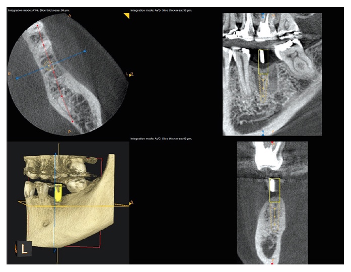
The CBCT scan (data volume) provides cross sections through various planes, allowing 3D evaluation of hard and soft tissues. There are three orthogonal planes (Figure 1):
- Axial or horizontal plane provides cross sections of the data volume from top to bottom of the FOV
- Coronal or frontal or side view provides cross sectional views from front to back of the FOV
- Sagittal view provides cross sections from buccal to lingual, or left to right of the FOV.
Besides the three planes, there is also a 3D rendering (Figure 1, upper right).
A structured or systematic approach for reading a CBCT scan is recommended because there is a huge amount of anatomy contained within the scanned volume, and unless a structured approach is used, it is likely you will miss some information that could impact your diagnosis and treatment planning.
 CBCT data volume: review protocol
 CBCT data volume: review protocol
Each section of the data volume (FOV) must be reviewed and analyzed for possible clinically significant findings. This requires discipline, and it may take some time and practice to establish a pattern so as to make it almost second nature to follow this process.
In reviewing each of the anatomical structures in the FOV, special attention is paid to the “main complaint,” or the reason for the scan acquisition. The purpose of a structured reviewing process is to prevent overlooking significant diagnostic findings that may have an impact on the success or predictability of outcome of implant treatment and any other abnormalities that may lead to medico-legal actions.
The following reviewing protocol is based on the Carestream Kodak CS 9300 3D unit.
Clinical history
Start by reviewing the clinical history. What is the purpose of the data acquisition? Which teeth have been removed (and when?) that explain areas of bone loss with healing and/or residual alveolar bone defects?
Establish whether previous bone grafts or socket augmentations were done previously.
Orientation
Open the patient’s data volume. The default scan is usually on “orthogonal slicing” (Figure 2). Select “curved slicing” on the upper menu bar (Figure 3). Identify the three cross-sectional planes: Axial is upper left, sagittal is upper right, 3D rendering is lower left, and coronal is lower right (Figure 3). Identify where left and right, and buccal and lingual are as well as the horizontal (yellow) and vertical (blue and red) lines, and cursor buttons used for scouting and orientation vertically and horizontally along the planes.
Scout the axial (top to bottom) (yellow cursor line), coronal (front to back) (red cursor line), and sagittal (right to left) (blue cursor line) planes by moving the horizontal and vertical lines to orient yourself where you are and what you are looking at.


Set arch on the axial plane
Select the “manually create arch” icon on the tool menu on the left side of the image (Figure 4). A text box will pop up with prompt: “Delete previous arch.” Select OK. Move the blue cursor button on the horizontal bar below the axial cross section to get a good cross-sectional view of the roots on the arch (Figure 4). Click and draw an arch through the center of the root from left to right side (Figure 5).
Scouting the coronal cross section
Go to the sagittal plane (upper right cross section) (Figure 6). Move the vertical cursor (blue) from left to right on the FOV to review the coronal cross section (lower right) to identify clinically significant pathosis and neurovascular structures (Figure 6). Return again to the center of the area of interest with the vertical line in the sagittal cross-sectional plane.
Scouting the sagittal cross section
Go to the coronal cross section (lower right) (Figure 6). Move the red cursor of the vertical line from buccal to lingual (left to right) to review the upper sagittal cross section to identify any clinically significant pathosis and neurovascular structures. Return again to the center of the area of interest with the red vertical line in the coronal cross-sectional plane (Figure 6). At this stage, the “nerve canal tool” icon can be activated to plot the inferior alveolar nerve (Figure 7).
Review area of interest (implant site)
Lastly, scout and assess the region of interest (implant site) and adjacent teeth. Note any morphological abnormalities, neurovascular structures, anatomical structures (sinus, nasal), and residual alveolar ridge morphology or other clinically significant findings that may have an impact on implant treatment planning.
Move the horizontal line of the sagittal cross section (upper right) to 1 mm below the crestal level (Figure 6).
Implant treatment planning
Software tools can be applied to facilitate implant treatment planning. Activate the “measurement mode” icon in the “tools menu” (Figure 7). Go to the axial cross section (upper left), and click buccal and then palatal to measure the bucco-palatal width. Move to the sagittal cross section (upper right), and click mesial to distal of the implant site to measure the saddle length of the residual alveolar ridge (Figure 7). Select the coronal cross section (lower right), and measure the width and length of the residual alveolar bone (Figure 7). If the implant site is in the lower posterior mandible, then measure from the crestal level to 2 mm above the inferior alveolar nerve. The correct implant diameter and length can now be selected for this implant site.
Virtual implant selection and placement
Position the vertical line in the correct position of the osteotomy site in the coronal cross section (lower right). Activate the “implant placement tool” icon in the “tool menu” (Figure 8). Select the desired implant type, diameter, and length according to the abovementioned measurements. Adjust fine tuning of the implant in its correct 3D position by checking all three planes (axial, sagittal, and coronal (Figure 9).
A stent can also be used to position the vertical line in the correct position where the implant must be placed (Figure 10).
Check placement of the implant in all three planes to assess that the cortical plate, anatomical structures — such as the sinus and nasal cavity, neurovascular structures, and neighboring teeth — are not violated, and that the implant is placed in the correct 3D position in the residual alveolar bone for optimal implant stability and a successful prosthetic restoration.
Go to the menu bar above the sagittal cross section (upper right), select “set integration,” and select 15 mm on the scroll-down menu to activate ray sum for the sagittal cross section to simulate a typical panoramic X-ray. The magnification tool can be used to better assess the area of interest (Figure 11). The virtual implant planning and placement can now be communicated visually and discussed with the patient.
Conclusion
CBCT imaging technology computer software has significantly increased the accuracy and efficiency of diagnostic and treatment capabilities, thereby offering an unparalleled diagnostic approach when dealing with previously challenging unknown anatomical and/or pathological entities in implant dentistry.
This article proposes a protocol for performing a structured review and reading CBCT data volume to ensure that pathology or critical anatomical structures are not missed that may impact on or enhance diagnosis, treatment planning, and treatment outcomes.
The next article in this series will look more closely at the specific application of CBCT imaging in implant dentistry.
Dr. Jay B. Reznick wrote important information regarding CBCT, as well as CAD/CAM, 3D printing, and guided implant surgery in his article. https://implantpracticeus.com/case-studies/integration-cad-cam-3d-imaging-3d-printing-guided-implant-surgery-treat-traumatic-dental-injury-surgical-practice/.
References
- American Association of Endodontists (AAE) and American Association of Oral Maxillofacial Radiologists (AAOMR) joint position statement. J Endod. 2011;37(2):274-277.
- Abarca M, Steenberghe D, Malevez C, De Ridder J, Jacobs R. Neurosensory disturbances after immediate loading of implants in the anterior mandible: an initial questionnaire approach followed by a psychophysical assessment. Clin Oral Investig. 2006;10(4):269-277.
- Adibi S, Zhang W, Servos T, O’Neill PN. Cone beam computed tomography in dentistry: what dental educators and learners should know. J Dent Educ. 2012;76(11):1437-1442.
- Alamri HM, Sadrameli M, Alshalhoob MA, Sadrameli M, Alshehri MA. Applications of CBCT in dental practice: a review of the literature. Gen Dent. 2012;60(5):390-400.
- Angelopoulos C. Anatomy of the maxillofacial region in the three planes of section. Dent Clin North Am. 2014;58(3):497-521.
- Academy of Osseointegration. 2010 Guidelines of the Academy of Osseointegration for the provision of dental implants and associated patient care. Int J Oral Maxillofac Implants. 2010;25(3):620-627.
- Asaumi R, Kawai T, Sato I, Yoshida S, Yosue T. Three-dimensional observations of the incisive canal and the surrounding bone using cone-beam computed tomography. Oral Radiol. 2010;26(1):20-28.
- Bagheri SC, Meyer RA. Management of mandibular nerve injuries from dental implants. Atlas Oral Maxillofac Surg Clin North Am. 2011;19(1):47-61.
- Benavides E, Rios HF, Ganz SD, et al. Use of cone beam computed tomography in implant dentistry: the International Congress of Oral Implantologists consensus report. Implant Dent. 2012;21(2):78-86.
- Bornstein MM, Al-Nawas B, Kuchler U, Tahmaseb A. Consensus statements and recommended clinical procedures regarding contemporary surgical and radiographic techniques in implant dentistry. Int J Oral Maxillofac Implants. 2014;29(Suppl):78-82.
- Bornstein MM, Scarfe WC, Vaughn VM, Jacobs R. Cone beam computed tomography in implant dentistry: a systematic review focusing on guidelines, indications, and radiation dose risks. Int J Oral Maxillofac Implants. 2014;29 (Suppl):55-77.
- Buser D, Belser UC, Wismeijer D, eds. Implant Therapy in the Esthetic Zone: Single-tooth Replacements. Berlin: Quintessence Publishing; 2007.
- Carmeli G, Artzi Z, Kozlovsky A, Segev Y, Landsberg R. Antral computerized tomography pre-operative evaluation: relationship between mucosal thickening and maxillary sinus function. Clin Oral Implants Res. 2011;22(1):78-82.
- Carter L, Farman AG, Geist J, et al.; American Academy of Oral and Maxillofacial Radiology. American Academy of Oral and Maxillofacial Radiology executive opinion statement on performing and interpreting diagnostic cone beam computed tomography. Oral Surg Oral Med Oral Pathol Oral Radiol Endod. 2008;106(4):561-562.
- Chan HL, Leong DJ, Fu JH, et al. The significance of the lingual nerve during periodontal/implant surgery. J Periodontol. 2010;81(3):372-377.
- Curley A, Hatcher DC. Cone beam CT—anatomic assessment and legal issues: the new standards of care. Todays FDA. 2009;22(4):52-55, 57-59, 61-63.
- Danesh-Sani SA, Movahed A, ElChaar E, Chan KC, Amintavaloti N. Radiographic evaluation of maxillary sinus lateral wall and posterior superior alveolar artery anatomy: a cone-beam computed tomographic study. Clin Implant Dent Relat Res. 2017;19(1):151-160.
- Dawson A, Chen S, Buser D, Cordaro L, Martin W, Belser U. The SAC Classification in Implant Dentistry. Berlin, Germany: Quintessence Publishing; 2009.
- Deeb, G, Antonos L, Tack S, Carrico C, Laskin D, Deeb JG. Is Cone-Beam Computed Tomography Always Necessary for Dental Implant Placement? J Oral Maxillofac Surg. 2017;75(2):285-289.
- Farman AG. Self-referral—an ethical concern with respect to multidimensional imaging in dentistry? J Appl Oral Sci. 2009;17(5).
- Fortin T, Camby E, Alik M, Isidori M, Bouchet H. Panoramic images versus three-dimensional planning software for oral implant planning in atrophied posterior maxillary: a clinical radiological study. Clin Implant Dent Relat Res. 2013;15(2):198-204.
- Ganz SD. Cone beam computed tomography-assisted treatment planning concepts. Dent Clin North Am. 2011;55(3): 515-536.
- Givol N, Chaushu G, Halamish-Shani T, Taicher S. Emergency tracheostomy following life-threatening hemorrhage in the floor of the mouth during immediate implant placement in the mandibular canine region. J Periodontol. 2000;71(12):1893-1895.
- Greenstein G, Carpentieri JR, Cavallaro J. Dental Cone-Beam Scans: Important Anatomic Views for the Contemporary Implant Surgeon. Compendium Cont Educ Dent. 2015;36(10):735-741.
- Greenstein G, Tarnow D. The mental foramen and nerve: clinical and anatomical factors related to dental implant placement: a literature review. J Periodontol. 2006;77(12):1933-1943.
- Greenstein G, Cavallaro J, Romanos G, Tarnow D. Clinical recommendations for avoiding and managing surgical complications associated with implant dentistry: a review. J Periodontol. 2008;79(8):1317-1329.
- Grey EB, Harcourt D, O’Sullivan D, Buchanan H, Kilpatrick NM. A qualitative study of patients’ motivations and expectations for dental implants. Br Dent J. 2013;214(1): E1.
- Gupta A, Rathee S, Agarwal J, Pachar RB. Measurement of Crestal Cortical Bone Thickness at Implant Site: A Cone Beam Computed Tomography Study. J Contemp Dent Pract. 2017;18(9):1-5.
- Hatcher DC, Dial C, Mayorga C. Cone beam CT for pre- surgical assessment of implant sites. J Calif Dent Assoc. 2003;31(11):825-833.
- Harris D, Horner K, Gröndahl K, et al. E.A.O. guidelines for the use of diagnostic imaging in implant dentistry 2011. A consensus workshop organized by the European Association for Osseointegration at the Medical University of Warsaw. Clin Oral Implants Res. 2012;23(11):1243-1253.
- Jacobs R, Quirynen M. Dental cone beam computed tomography: justification for use in planning oral implant placement. Periodontol 2000. 2014;66(1):203-213.
- Janner SF, Caversaccio MD, Dubach P, et al. Characteristics and dimensions of the Schneiderian membrane: a radiographic analysis using cone beam computed tomography in patients referred for dental implant surgery in the posterior maxilla. Clin Oral Implants Res. 2011;22(12):1446-1453.
- Juodzbalys G, Wang HL, Sabalys G, Sidlauskas A, Galindo-Moreno P. Inferior alveolar nerve injury associated with implant surgery. Clin Oral Implants Res. 2013;24(2):183-190.
- Kalpidis CD, Setayesh RM. Hemorrhaging associated with endosseous implant placement in the anterior mandible: a review of the literature. J Periodontol. 2004;75(5):631-645.
- Klokkevold PR. Cone beam computed tomography for the dental implant patient. J Calif Dent Assoc. 2015;43(9): 521-530.
- Kobayashi K, Shimoda S, Nakagawa Y, Yamamoto A. Accuracy in measurement of distance using limited cone-beam computerized tomography. Int J Oral Maxillofac Implants. 2004;19(2):228-231.
- Lekholm U, Zarb GA. Patient selection and preparation. In: Brånemark PI, Zarb GA, Albrektsson T, eds. Tissue-Integrated Prostheses: Osseointegration in Clinical Dentistry. Chicago, IL: Quintessence Publishing; 1985.
- Mah P, Reeves TE, McDavid WD. Deriving Hounsfield units using grey levels in cone beam computed tomography. Dentomaxillofac Radiol. 2010;39(6):323-335.
- Makins SR. Artifacts interfering with interpretation of cone beam computed tomography images. Dent Clin North Amer. 2014;58(3):485-495.
- Mallya SM, Tetradis S. Trends in dentomaxillofacial imaging. J Calif Dent Assoc. 2015;43(9):501-502.
- Mallya SM. Evidence and Professional Guidelines for Appropriate Use of Cone Beam Computed Tomography. J Calif Dent Assoc. 2015;43(9):512-520.
- Miles DA, Danforth RA. Reporting findings in the cone beam computed tomography volume. Dent Clin North Amer. 2014;58(3):687-709.
- Misch CE. Contemporary Implant Dentistry. 3rd ed. St Louis, MO: Mosby Elsevier; 2008.
- Mraiwa N, Jacobs R, Van Cleynenbreugel J, et al. The nasopalatine canal revisited using 2D and 3D CT imaging. Dentomaxillofac Radiol. 2004;33(6):396-402.
- Oliveira ML, Tosoni GM, Lindsey DH, et al. Influence of anatomical location on CT numbers in cone beam computed tomography. Oral Surg Oral Med Oral Pathol Oral Radiol. 2013;115(4):558-564.
- Oliveira ML, Tosoni GM, Lindsey DH, et al. Assessment of CT numbers in limited and medium field-of-view scans taken using Accuitomo 170 and Veraviewepocs 3De cone-beam computed tomography scanners. Imaging Sci Dent. 2014;44(4):279-285.
- Paquette DW, Brodala N, Williams RC. Risk factors for endosseous dental implant failure. Dent Clin North Amer. 2006;50(3):361-374.
- Park YB, Jeon HS, Shim JS, Lee KW, Moon HS. Analysis of the anatomy of the maxillary sinus septum using 3-dimensional computed tomography. J Oral Maxillofac Surg. 2011; 69(4):1070-1078.
- Parks ET. Cone beam computed tomography for the nasal cavity and paranasal sinuses. Dent Clin North Amer. 2014;58(3):627-651.
- Parsa A, Ibrahim N, Hassan B, et al. Influence of cone beam CT scanning parameters on grey value measurements at an implant site. Dentomaxillofac Radiol. 2013;42(3).
- Patel S, Durack C, Abella F, et al.; European Society of Endodontology position statement: the use of CBCT in endodontics. Int Endod J. 2014;47(6):502-504.
- Pauwels R, Nackaerts O, Bellaiche N, et al; SEDENTEXCT Project Consortium. Variability of dental cone beam CT grey values for density estimations. Br J Radiol. 2013;86(1021).
- Pauwels R, Jacobs R, Singer SR, Mupparapu M. CBCT-based bone quality assessment: are Hounsfield U units applicable? Dentomaxillofac Radiol. 2015;44(1).
- Ribeiro-Rotta RF, Lindh C, Pereira AC, Rohlin M. Ambiguity in bone tissue characteristics as presented in studies on dental implant planning and placement: a systematic review. Clin Oral Implants Res. 2011;22(8):789-801.
- Romanos GE, Greenstein G. The incisive canal. Considerations during implant placement: case report and literature review. Int J Oral Maxillofac Implants. 2009;24(4):740-745.
- Sakhdari S, Panjnoush M, Eyvazlou A, Niktash A. Determination of the Prevalence, Height, and Location of the Maxillary Sinus Septa Using Cone Beam Computed Tomography. Implant Dent. 2016;25(3):1-6.
- Sato S, Arai Y, Shinoda K, Ito K. Clinical application of a new cone-beam computerized tomography system to assess multiple two-dimensional images for the preoperative treatment planning of maxillary implants: case reports. Quintessence Int. 2004;35(7):525-528.
- Scarfe WC, Farman AG. What is cone-beam CT and how does it work? Dent Clin North Amer. 2008;52(4):707-730.
- Scherer MD. Presurgical implant-site assessment and restoratively driven digital planning. Dent Clin North Amer. 2014;58(3):561-595.
- Shanbhag S, Karnik P, Shirke P, Shanbhag V. Cone-beam computed tomographic analysis of sinus membrane thickness, ostium patency, and residual ridge heights in the posterior maxilla: implications for sinus floor elevation. Clin Oral Implant Res. 2014;25(6):755-760.
- Temmerman A, Hertelé S, Teughels W, et al. Are panoramic images reliable in planning sinus augmentation procedures? Clin Oral Implants Res. 2011;22(2):189-194.
- Tipton WL, Metz P. Three dimensional computed technology – a new standard of care. Int J Orthod Milw 2008;19(1):15-21.
- Tyndall DA, Price JB, Tetradis S, et al.; American Academy of Oral and Maxillofacial Radiology. Position statement of the American Academy of Oral and Maxillofacial Radiology on selection criteria for the use of radiology in dental implantology with emphasis on cone beam computed tomography. Oral Surg Oral Med Oral Pathol Oral Radiol. 2012;113(6):817-826.
- Valiyaparambil JV, Yamany I, Ortiz D, et al. Bone quality evaluation: comparison of cone beam computed tomography and subjective surgical assessment. Int J Oral Maxillofac Implants. 2012;27(5):1271-1277.
- Yepes JF, Al-Sabbagh M. Use of cone-beam computed tomography in early detection of implant failure. Dent Clin North Amer. 2015;59(1):41-50
- Zinman EJ, White SC, Tetradis S. Legal considerations in the use of cone beam computer tomography imaging. J Calif Dent Assoc. 2010;38(1):49-56
Stay Relevant With Implant Practice US
Join our email list for CE courses and webinars, articles and mores
