Dr. Charles Schlesinger explains how the Unifi MI’s unique threads promote greater implant stability.
Dr. Charles D. Schlesinger discusses the science behind the Unifi MI implant
Why are we continuing to use dental implants that rely upon a wedging mechanism to gain primary stability? Though dental implants have an extremely high success rate and are a predictable treatment modality, is it possible that it could be improved upon?
I would like to elaborate upon a new treatment modality that is not only a revolutionary way to fixate an implant to bone, but an evolution of the dental implant itself.
The basic macro structure of modern dental implant has not changed much since its inception. The implant that Brånemark first placed in his patients in 1965 when the original Brånemark implant was created was cylindrical; later on tapered forms appeared.1 We have seen the use of different thread designs with the top three today being V-threads, square threads, and reverse buttress styles. To address the ever-present issue of crestal bone loss, implants have evolved by moving the connection from an external position to internal, moving the platform emergence from the outside of the implant circumference to inside it by platform switching. A host of collar designs – smooth, polished, machined, micro-threaded, tissue level, and bone level have all been utilized. All this being said, the macro structure of these implants all function as a compression, friction-fit screw in the osteotomy to achieve primary stability at placement. This type of compression stability results in detrimental short-term sequalae that are not overcome until osseointegration is completed.
With its origins in heavy industry, a unique thread design is able to achieve the union of two pieces of metal without any damage to each piece. In a nutshell, it has the ability to “stitch” two pieces into one with an incredibly strong union. In 2015, Osteocentric Technologies (Austin, TX) was founded, and the concept of Unifi MI was born. This unique and revolutionary thread design was first utilized for fixation devices in orthopedics. Following the success in that field, the patented thread design was introduced into adjacent verticals including trauma, recon, limb salvage, spinal, and veterinary. Today, over 55,000 Unifi MI devices have been placed at over 80 Level 1 teaching centers across the United States. Today, we are on the verge of having this incredible technology introduced in the world of dental implants.
Traditional implants
To understand how the Unifi MI works, you must first understand how traditional implant and thread designs work. A traditional implant, for the past 50 years, whether a tapered body or parallel walled implant, relies upon wedging forces to achieve primary stability, essentially the same wedging mechanism that occurs when you put a screw into a piece of wood. This wedging facilitates what is called a friction fit. This friction fit occurs as the result of the osteotomy drill producing an osteotomy that is not only smaller than the major diameter of the implant, but also smaller than the minor diameter. Add to this the fact that many of the implants available today are tapered in their design. The implant plows its way through bone, trapping bone fragments and creating not only compressive forces, but micro-fractures2 as it travels down the osteotomy and settles into its final position with a high torque value and a perceived high primary stability.
A high insertion torque equates to a high compression of the bone, and bone is not wood — it is a living vital tissue that responds negatively to high compressive pressure, as seen during orthodontic movement.3 Massive remodeling occurs in response to the trauma incurred.

The most popular thread designs used today fall into the three categories mentioned above: V-threads, square threads, and reverse buttress threads. When an implant is first placed, all of its stability is achieved by the aforementioned wedging and the action of the threads engaging bone around the perimeter of the osteotomy. The forces these threads create as they are driven through the bone are focused in a perpendicular fashion from the face of the thread and are compressive (Figure 1). Under immediate load, prior to osseointegration, these threads produce compressive forces on the compression side and lose engagement on the side 180º from this compression side. This is more evident in soft bone scenarios and in immediate placement situations where engagement of an implant may only be at the apex and against one wall of a socket. Since P=F/A, the small areas of force concentration result in very high localized pressure points that produce high pressure and eventually resorption of bone.
Once the implant is integrated, axial and off-axis forces are distributed to the bone by these very threads and the portions of the implant body between these threads. The majority of these forces are confined to the crestal 5 mm of the implant. Numerous studies have backed up this concept through finite element analysis and photoelastic experiments; research has shown that the stress distribution within a bone-to-titanium implant relationship is concentrated in the implant’s crestal region4 (Figure 2).

Rieger, et al.,5 and Inou, et al.,6 based on previously published physiologic thresholds, reported that in their experiments bone resorption occurred in regions where the stress concentration was under or over the physiologic limits. In regions where the stress was within those limits, the bone maintained its morphology.
How Unifi MI is different
Unifi MI stands for Unifi Mechanical Integration. The Unifi threads interlock a flank of bone between them and not only reduces the movement of the implant (Figure 3), but also distributes forces in a very different way than traditional threads or implants. Let me make this clear; this is not a replacement for the development of osseointegration or secondary implant healing. This is a way to achieve outstanding primary stability, resistance to micro-motion, and better stress distribution in the peri-implant bone not only at the early phases of treatment, but also for the entire life of the implant in function.
The development of Unifi MI for dentistry
Taking cues from the tremendous successes in the medical field, a project started a few of years back with idea to apply this technology to dental implants. The forces the implant will be exposed to are similar to those in medicine with regard to toggling forces, but would differ in axial forces. In dentistry, these forces would be exerted in a compressive fashion down the implant body as opposed to the screws used in the other medical disciplines which are subjected instead to massive pull-out forces. Due to this fundamental difference, the usually “upward” facing Unifi threads were flipped into a downward facing position. To assure there would not be any mechanical disadvantage or change in stress distribution, finite element analysis (FEA) was conducted (Figure 4).

The configuration of the implant progressed through a series of macro configurations starting with a design very close to the design used in orthopedics. The implant developed over time through testing to the current design (Figure 5). The prototype implants are in the following sizes: 3.7 mm, 4.2 mm, and 5.5 mm diameters with lengths ranging from 8 mm-12 mm in length (Figure 6). Likely by the time this article is published, FDA clearance will be completed.


The osteotomy
Implant systems on the market today, by design, prepare an osteotomy that is smaller than or equal to the minor diameter of the implant in order to maximize not only thread contact, but allow the implant body to compress the adjacent bone for increased stability. This increased stability comes at a price — The greater the geometrical differences between the implant the greater the geometrical differences between the implant and bone cavity, the greater the bone area that would be compressed, and the greater the stress generated. Duyck, et al., stated that the difference in size between the implant collar and the prepared cavity plays an important role in bone strains and stresses when an implant is inserted.7
As seen in the implant collar areas in Models 1 and bone cavity, the greater the bone area that would be compressed, and the greater the stress generated8 (Figure 7).
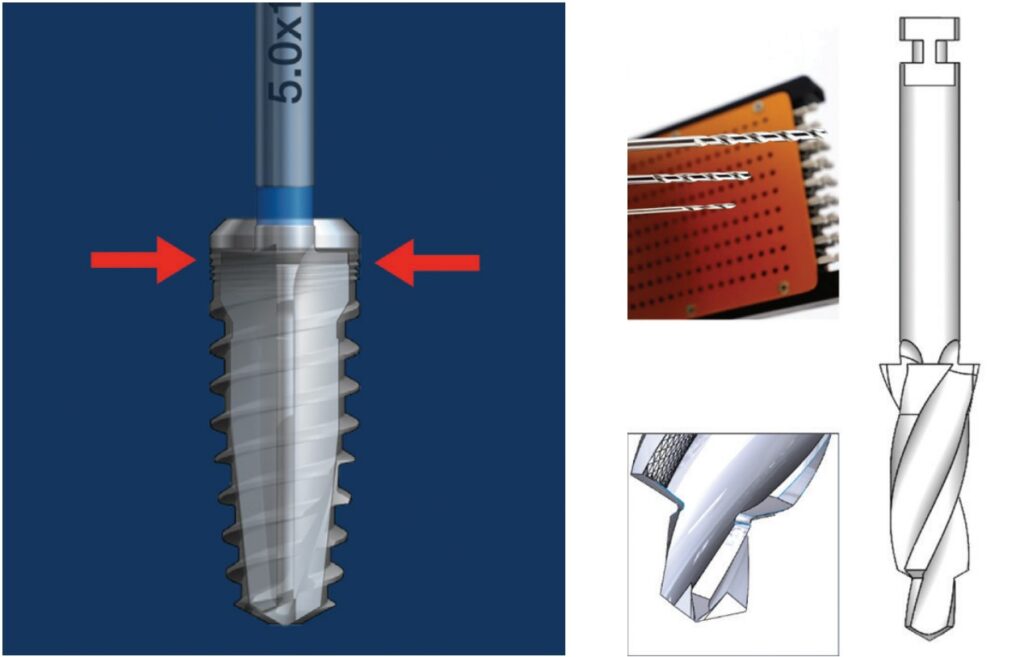
The Osteocentric osteotomy formers are a direct evolution of the proprietary Osteoguard drills used in orthopedic bone preparation (Figure 8). These drills are designed in such a way that they have shown to produce less heat generation, clear debris efficiently, and have precise drilling with better tracking.9 We can deduce from this that less injury to the bone is produced when creating the osteotomy.
When preparing the dental osteotomy, the drill will “over-drill” by approximately .1 mm larger than the minor diameter on all sides, thereby eliminating any compression by the implant body when inserting and seating in final position within the alveolus (Figure 9). The implant body will travel down the osteotomy aggressively loading the bone between the threads instead of radially. This type of loading produces much higher stability without the side effect of negative compressive forces.

By inserting the implant in this fashion, it is only the self-tapping Unifi threads that cut or tap their way into the bone. This is designed to prevent radial compressive forces which can cause necrosis and remodeling of the bone around the implant during healing. This remodeling is the major contributor to the dip in stability that occurs around 3-5 weeks after placement of an implant (Figure 10).10

FEA testing head-to-head with traditional implant design
Finite Element Analysis (FEA) is the use of calculations, models, and simulations to predict and understand how an object might behave under various physical conditions. Engineers use FEA to find vulnerabilities in their design prototypes, and this type of testing is used extensively these days in dental implant design and research.
Overall stress distribution was looked at under axial and lateral loading scenarios. It has been widely accepted and proven out that the majority of Von Mises stresses are confined to the top 5 mm of a dental implant even after osseointegration. When Las Casas studied multiple types of implants in both vertical and angled placement, implants presented low stress on the medullary bone area, indicating that the major concentration was actually in the cortical layer, which agrees with previous results.11
When comparing both a reverse buttress and V-threaded implant against an implant with Unfi threads, we can see that the traditional implant thread designs confirm the location of stresses reported in the literature. The Unifi threaded implant is designed to distribute the stress down the long axis of the whole implant, thereby dissipating forces over a much broader area resulting in a minimal concentration of forces at the crestal region (Figure 11).

This distribution is facilitated by the ability of the threads to not only lock the bone to the implant body, but also change the forces that the individual threads produce. The force vectors between traditional and Unifi threads are very different. As stated earlier, with all three types of traditional threads, the forces are directed perpendicularly into the bone, where the Unifi threads use what is called “force vectoring” to have a very different stress pattern (Figure 12).

The overall resistance to movement was tested in 15 PFC Sawbones (Sawbones Pacific Research, Vashon, Washington) which simulates D3 bone type. The ability to interlock with healthy bone circumferentially around the implant allows the threads to stabilize the implant from every direction and ultimately resist displacement (Figure 13). When cycled 100,000 times with a 30º off-axis load, the results were dramatic (Figure 14).


When comparing implant designs using 2:1 implant analogs (for 5.5 mm diameter implants), this interlocked bone can be seen when backing an implant out of a Sawbones demo block (Figure 15). These “spirals” of bone demonstrate the bone preservation rather than crushing which is typically produced by an implant with a reverse buttress thread (Figure 16).

Different thread designs were compared to evaluate the amount of movement an implant has when subjected to lateral loads. Again, when compared to conventionally designed implants, the FEA showed that the Unifi threaded implant had less overall movement at abutment level (Figure 17).

Implants fail when the bony support around them cannot withstand the repeated forces generated by mastication. As the implant loses stability, and bone continues to resorb, the implant moves resulting in crestal bone loss. As crestal bone recedes, it changes the physics of the system. As the pivot point moves apically, the moment arm above the pivot point gets longer. This lengthening will produce higher loads, or a vertical cantilever, ultimately accelerating the bone loss until the implant is lost.
In 15PCF Sawbones blocks, there is a dramatic difference when comparing implant tracking and the force it takes to laterally displace the implant head-to-head against a reverse buttress style implant (Figures 18 and 19).

Cadaveric studies
In cadaveric studies, the results attained during FEA testing held true when observing the way these implants performed. The two-step drilling protocol to create the osteotomy was very precise. The length specific final drill followed the path of the pilot without wandering and with little resistance. If the bone quality was of the D1 kind, then intermediately sized drills were utilized in progression.
As an implant practitioner, I was trained to look for high torque when placing an implant. The amount of torque that occurs when placing an implant with Unifi threads is literally a fraction of those I normally see when placing implants that are on the market today. Lower insertion torques yield favorable survival rates with optimal marginal bone levels compared with the accepted norm.12
The insertion of the implants required very little torque, yet the stability was outstanding when tested with an Osstell Beacon (Osstell, Goteborg, Sweden) RFA device. This supported what was seen in testing with lower insertion torques and equal to higher ISQ values when compared to a reverse buttress-style tapered implant.
When conducting trials in extraction/immediate placement scenarios, the tracking of the drills and the Unifi threads prevented the implant from “wandering” out of the osteotomy or intended position. This type of displacement is prevalent in immediate placement as a traditional implant is pushed out of the path by anatomy. Overall, the results of these limited studies showed outstanding clinical performance during the surgical phase.
Discussion
Mechanical Integration is possible today, and its advantages span from placement through early healing — ultimately an advantage in the long term for implant success. Is it possible that for years we have been chasing a unicorn with regard to crestal bone loss? Or has the answer always been there, but was not obvious because the solution did not exist until now?
Might the answer to short term failure be the ability to mechanically integrate an implant to the bone and prevent forces from creating micromovement of greater than 150 microns during the remodeling phase and prevent soft tissue encapsulation and failure?
The loss of crestal bone or an implant, after loading prosthetically (assuming proper prosthetic restoration) could be prevented by the distribution of masticatory forces throughout the complete length of the implant rather than focusing it at the crest.
Current research is focusing on the role of bacteria in peri-implantitis. Ask yourself this: Why does a patient have one implant survive and one fail within the same oral environment? Could bacterial infiltration be an opportunistic infection which occurs when implant stress on the bone causes resorption? It is a true “chicken or the egg” scenario.
For 50 years, we have been looking for answers to explain crestal bone loss and failure. Why have we not looked at the fact that the root cause may be the very implant designs we utilize and the acceptance as doctrine, that the major forces on the implant-bone system must be focused at and just below the crest for the first 5mm?
 Charles D. Schlesinger DDS, FICOI, has been placing implants for the past 27 years and has been an implant educator for the last 17 years. After his residency programs at the VAMC San Diego and Los Angeles, he had a thriving private practice in San Diego for 14 years. In 2012, he relocated to New Mexico to become the Head of Education and Clinical Affairs and then Chief Operating Officer of a dental implant manufacturer. In 2016, he re-entered private practice where he treats patients in Albuquerque, New Mexico and continues to teach worldwide. He is the COO of Comfortable Dentistry 4U and a KOL for multiple companies.
Disclosure: Dr. Schlesinger is on the design team for Osteocentric Technologies.
- Abraham CM. A brief historical perspective on dental implants, their surface coatings and treatments. Open Dent J. 2014 May 16;8:50-55.
- Kotsakis GA, Romanos GE. Biological mechanisms underlying complications related to implant site preparation. Periodontol 2000. 2022 Feb;88(1):52-63.
- Norton M. Primary Stability: What Does it Mean? Implant Practice US. https://implantpracticeus.com/ce-articles/primary-stability-what-does-it-mean/. Accessed April 21, 2023.
- Stanley R. The Five Thread Guideline: A New Guideline for Predicting Primary Stability With Dental Implants. J Oral Implantol. 2020 Feb 1;46(1):81-86.
- Rieger MR, Adams WK, Kinzel GL. A finite element survey of eleven endosseous implants. J Prosthet Dent. 1990 Apr;63(4):457-65.
- Inou N,Iioka Y,Fujiwara H,Maki K. Functional adaptation of mandibular bone. In: Hayashi K, Ishikawa H. Computational Biomechanics. Heidelberg, Germany: Springer-Verlag,1996:23-42.
- Duyck J, Corpas L, Vermeiren S, Ogawa T, Quirynen M, Vandamme K, Jacobs R, Naert I. Histological, histomorphometrical, and radiological evaluation of an experimental implant design with a high insertion torque. Clin Oral Implants Res. 2010 Aug;21(8):877-884.
- Udomsawat C, Rungsiyakull P, Rungsiyakull C, Khongkhunthian P. Comparative study of stress characteristics in surrounding bone during insertion of dental implants of three different thread designs: A three-dimensional dynamic finite element study. Clin Exp Dent Res. 2018 Dec 26;5(1):26-37.
- Pye JL, Garcia TC, Kapatkin AS, Stover SM. Comparison of Drilling, Screw Insertion and Pullout Variables of Biaxial and Uniaxial Thread Self-Tapping 3.5 mm Cortical Bone Screws in Cadaveric Equine Third Metacarpal Bone. In: Proceedings from the Veterinary Orthopedic Society 2020 Conference; February 1-8,2020.
- Schlesinger C. RFA and its Use in Implant Dentistry. Chapter in Current Concepts in Dental Implantology: From science to clinical care. https://www.intechopen.com/chapters/77842. Published August 2021. Accessed April 21, 2023.
- Las Casas EB, Ferreira PC, Cimini CA Jr, Toledo EM, Barra LP, Cruz M. Comparative 3D finite element stress analysis of straight and angled wedge-shaped implant designs. Int J Oral Maxillofac Implants. 2008 Mar-Apr;23(2):215-225.
- Norton MR. The Influence of Low Insertion Torque on Primary Stability, Implant Survival, and Maintenance of Marginal Bone Levels: A Closed-Cohort Prospective Study. Int J Oral Maxillofac Implants. 2017 Jul/Aug;32(4):849-857.
Stay Relevant With Implant Practice US
Join our email list for CE courses and webinars, articles and mores