Dr. Steven Vorholt shows that when precision is crucial, digital imaging technologies allow for visualization and foresight.
Dr. Steven Vorholt illustrates guided immediate implant surgery on teeth Nos. 19 and 18
Both immediate implant placement and fully guided implant placement are becoming more popular options for surgical approaches. Combining the two is a win-win and allows a shortened treatment timeline while still maintaining complete control for the best restoratively driven placement. Dentists investing in new digital technologies in-house can predictably and quickly plan, design, and execute guided immediate implant surgeries where precision is crucial. Implementing a digital workflow can make implant surgeries more efficient, more profitable, and more predictable. Digital imaging technologies allow for unparalleled visualization and foresight, while in-house 3D-printing and CAD/CAM solutions bring the restorative portion under the same roof.
Cone beam computed tomography (CBCT) and digital intraoral scanning systems simplify treatment planning and help avoid surgical complications in advance. Rather than separating the surgical and restorative aspects of the treatment, combining the CBCT and the intraoral scan of the patient’s dentition leads to restoratively driven implant placement and makes the entire process more predictable.
Planning alone is only as good as the clinician’s surgical skills. Knowing the location of possible complications is a huge advantage, but using surgical guides further minimizes risk. Using the combined radiographs and models to design a surgical stent, which can be 3D-printed and used during surgery, and designing the surgical stent based on the planned ideal position on the computer from start to finish mean more control and confidence at the actual surgery. Bringing the digital placement of the implant into the operatory allows your surgeries to be performed with more control and confidence.
Placing the implant exactly as planned makes the restorative portion of the treatment very straightforward. In-office CAD/CAM systems allow the dentist to take digital impressions, design the final prosthesis, and fabricate it without outsourcing. This workflow is impressive to patients and is more efficient and cost-effective for the dental team. Often this process can even be accomplished during the day of surgery to further speed up the treatment timeline.
In conclusion, new digital technologies and techniques help establish an optimized workflow for in-house surgeries and restorations. The following case highlights how I’ve used immediately guided digital protocols for the surgery and final restoration.
Case presentation and review


A healthy 69-year-old Caucasian male patient presented at a regular hygiene exam with a recent history of “on-and-off pain” from the lower left quadrant (Figure 2). The patient’s health history detailed controlled high blood pressure, controlled gastric reflux, and a history of arthritis.
Routine bitewing radiographs and periapical radiographs (Figure 1) revealed gross recurrent decay along the distal margin of a previously directly repaired metal crown margin. Food was occasionally getting trapped under the gum distal to the tooth and causing irritation. The tooth was deemed nonrestorable due to caries extending to the bone level and the margin of the decay being on the distal root. A recommendation was made to have the tooth removed and replaced with a dental implant. An alginate impression of the lower jaw was taken and scanned using the Shining 3D® DS-EX desktop scanner (Shining 3D®, San Francisco, California), and a 11 x 10 cm CBCT was exposed with a Dentsply Sirona Orthophos SL 3D (Dentsply Sirona, Charlotte, North Carolina) machine.


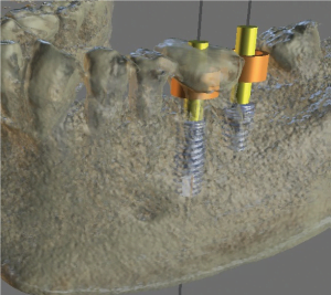


The digitized model (Figure 3) was loaded in the Blue Sky Bio (Libertyville, Illinois) digital implant planning software Blue Sky Plan. Tooth No. 19 was digitally extracted (Figure 4) to allow for the design of a surgical guide for the immediate placement. The patient had been missing tooth No. 18 for over 5 years and was encouraged to replace both teeth in one surgical appointment. Implants were planned in the software to be restoratively driven and parallel (Figures 5-7A). The mesial root space of tooth No. 19 was parallel to the root of tooth No. 20 and was utilized in the planned location of the 5.0 x 13 mm Blue Sky Bio Bio|Max dental implant. Figure 7 shows the use of the native bone apical to the mesial root socket for added initial stability. Tooth No. 18 was planned for a 5.0 mm x 8 mm Blue Sky Bio Bio|Max implant into the healed ridge of the second molar space. Tooth No. 17 later had enameloplasty performed on the mesial surface to accommodate two screw-retained restorations.


The digital plan for the implant locations is viewed utilizing the parallel root space of tooth No. 19 and the healed site for tooth No. 18 (Figures 8 and 9). A longer implant for tooth No. 18 (Figure 10) could have been used, but I have found no advantage of additional length past 8 mm in a healed site and wanted to avoid a longer “wag” factor being introduced into the system, which could amount to the No. 18 implant being difficult to restore if the dense lingual cortical plate or the distal root socket of No. 19 interfered with the guided placement. The guide was exported (Figure 7B) and printed on a MoonRay S 3D Printer (SprintRay, Los Angeles, California) using FDA-approved surgical guide resin. Initial treatment plan to being ready for surgical appointment was less than 24 hours.


Tooth No. 19 was atraumatically removed by sectioning the roots and utilizing luxators and elevators to remove the two roots independently of each other (Figure 11). The guide seat was confirmed for fit and stability (Figure 12) and an intrasulcular incision for envelope flap one tooth mesial and distal to the surgical site. Implant No. 18 was placed first, and a Penguin RFA device was used to record the implant stability quotient (ISQ) of 76 (Figure 13). The osteotomy was completed for tooth No. 19 and corticocancellous 50:50 allograft mix (Maxxeus™ Dental, Kettering, Ohio), mixed with fusion bone binder (Woodland Hills Pharmacy, Woodland Hills, California), was placed in the socket for No. 19 (Figure 14). The guide was replaced, and the final osteotomy drill run at 50 rpm in reverse without water to push the graft material apical and outward from the osteotomy (Figure 15). The 5.0 x 13 mm BSB Bio|Max implant was placed and ISQ recorded at 78. Both implants torqued out >30Ncm and had cover screws placed. A large pericardium long-term resorbable membrane was tucked under the flap, and 3-0 PTFE suture material was used in a continuous double-interlocking design to approximate the flap (Figure 16).

as covering the molar in the mesial socket of the first molar. Figure molar implant is parallel to second premolar, and second molar implant splits the difference between third molar and first molar path of draw


Immediate post-op PA (Figure 17) and 5 x 5 cm quadrant CBCT was exposed (Figures 18-20) showing guided placement to be very close to the ideal planned placement. Implant No. 19 was placed 2 mm subcrestal to the remaining buccal plate of No. 19, and No. 18 was placed 1 mm subcrestal to the healed ridge. Figure 19 shows adequate distance between the implant and the inferior alveolar nerve (IAN) canal and midcrestal placement. Post-op instructions were given to the patient, and he was released. The surgical appointment lasted 1 hour.
The patient was seen for a 2-week follow-up and suture removal (Figure 21), and he reported mild discomfort for the first 2 days. The patient also reported that OTC ibuprofen was enough to mask any discomfort, and that he had not experienced any problems since. Pericardium membrane was still intact and buried under the flap; PTFE sutures were removed; and the patient was rescheduled for 4 months for uncovery and transmucosal healing abutment placement.


The patient returned 4½ months after original surgery date for uncovery. Tissue was fully healed and pericardium membrane was resorbed (Figure 22). The midcrestal incision was made, and No. 19 required bone profiling (Blue Sky Bio Bone Profile Kit) to get the healing abutment to fully seat. Transmucosal healing abutments were placed, and three interrupted gut sutures were used (Figures 23-24).
Two weeks after uncovery, the patient returned for final digital impressions. Healing abutments were removed (Figure 25), and the healthy keratinized gingiva surrounding the implants was visualized. Blue Sky Bio 1.8 mm collar tibases were placed on the implants, and Sirona Scan Caps were placed for digital impression (Figure 26). An impression was taken with CEREC Bluecam (Sirona Dentsply) with 4.5.1 software, healing abutments were replaced, and the patient was rescheduled for final delivery 3 days later.

CEREC scan caps placed on Blue Sky Bio 1.8 mm collar tibase. Scanned with CEREC Bluecam (Dentsply Sirona)


The scan was loaded in CEREC 4.5.1 software to design the screw-retained implant crowns. The distal contour of No. 19 was made parallel to the angulation of the No. 18 implant (Figure 27) to facilitate screw-retained restorations. The No. 19 implant crown was placed first and the No. 18 crown placed second. Contacts were refined (Figures 28 and 29) to be broad, long, and parallel to the insertion angulation of No. 18. The buccal view was compared to ensure it fits the patient’s occlusion (Figure 30).
Three days later, the patient returned for delivery of two screw-retained IPS e.max® crowns (Ivoclar Vivadent, Amherst, New York). The crowns were luted to the tibases outside the mouth with RelyX® Luting cement (3M ESPE, St. Paul, Minnesota) and cleaned of excess before insertion. Both crowns were inserted and contacts verified (Figure 31). Final seat PA (Figure 32) confirmed full seating of the implant crowns and good crestal bone levels at 5 months. Note the distal contour of No. 19 paralleling the implant insertion angulation of No. 18 just like the plan in CEREC software. The ability for the practitioners to design this themselves allows increased flexibility for restoring side-by-side implant restorations.
One-year follow-up photos and periapical radiograph (Figures 33 and 34) show that tissue is very healthy, the patient has reported no problems or food traps, and bone levels have been maintained. The crestal bone can be seen to possibly have condensed further after 1 year of loading the implants. The excursive occlusion is checked at each hygiene recall appointment (Figure 35) to account for occlusion changes to the remaining dentition that can affect implant contacts.
Final thoughts
Dental implant surgery can be made more efficient, more profitable, and more predictable with the use of digital technologies and digital-planning software. From the initial treatment planning, the surgical appointment, and through the final restoration, this entire process took place in-office with no outsourcing of materials or costs.


Precision is crucial to Dr. Ara Nazarian’s implant protocols. Read his insights about “Predictable immediate guided implant placement and restoration within your practice” here. https://implantpracticeus.com/case-studies/predictable-immediate-guided-implant-placement-and-restoration-within-your-practice/
Stay Relevant With Implant Practice US
Join our email list for CE courses and webinars, articles and mores