Educational aims and objectives
This self-instructional course for dentists aims to discuss an overview of guidelines and protocols for obtaining adequate primary stability for full-arch immediately loaded implant-supported rehabilitation.
Expected outcomes
Implant Practice US subscribers can answer the CE questions by taking the quiz online to earn 2 hours of CE from reading this article. Correctly answering the questions will demonstrate the reader can:
- Identify anatomic structures that are associated with the full-arch immediate-load protocol.
- Recognize characteristics about implant macro design that make them more favorable for increased primary stability.
- Recognize surgical techniques used to obtain primary stability.
- Realize protocols that serve as guidelines for repeatable and predictable immediate load.
Dr. Leke Olowokere shares his guidelines for immediately loaded full-arch implants.
Dr. Leke Olowokere offers guidelines for repeatable and predictable full-arch implant protocols
The concept of a full-arch, implant-supported, immediately loaded prosthetic has been well studied and has become a predictable treatment modality to provide the edentulous population, as well as individuals with terminal dentition, with an implant-supported restoration at the same time as implant placement.1 Of the many factors that need to be considered when planning an immediately loaded prosthetic, achieving primary stability is imperative. Here lies the challenge that the full-arch implantologist must be able to predictably and habitually overcome — obtaining sufficient primary stability utilizing implants that are mechanically fixated, biologically stable, and prosthetically driven. Primary stability can be quantified in multiple ways, but a common measurement is via torque values (in general, minimum values considered sufficient for immediate load include 30ncm per implant or 120ncm cumulative torque).2,3 The aim of this article is to provide the full-arch implantologist with a basic guideline of anatomical considerations, armamentarium, and finally surgical techniques to consider in order to obtain sufficient primary stability for full-arch immediately loaded implants.

Anatomical considerations
Evaluation of hard tissue quantity and quality (Figures 1 and 2) is a key diagnostic factor when determining potential sites for sufficient primary stability. The implant surgeon needs to be able to evaluate a patient’s CBCT to locate areas of hard tissue for dental implants to be placed in a prosthetically driven, mechanically fixed, and biologically stable position. This is done by identifying and evaluating the patient-specific variations of common anatomical structures such as the maxillary sinus, nasal aperture, neurovascular canals, and the bone density (classified as D1, D2, D3, or D4 bone by Misch). Common areas of bone used for full-arch immediately loaded implants in the maxilla include: the alveolar ridge and basal bone apical to extraction sockets, palatal walls, the piriform rim of the nasal aperture, and the nasal crest of the maxilla. Facial buttresses can also be suitable areas of implant anchorage. These include the nasomaxillary, zygomaticomaxillary, and pterygomaxillary buttresses as seen in Figure 3.

In the mandible, common anatomical sites suitable for anchorage include: the alveolar ridge and basal bone apical to extraction sockets, and in severely atrophic mandibles or mandibles with exceptionally soft trabecular bone, the inferior border of the jaw.
These anatomical landmarks will be further discussed later in this article as it relates to the surgical technique for obtaining satisfactory primary stability.
Armamentarium
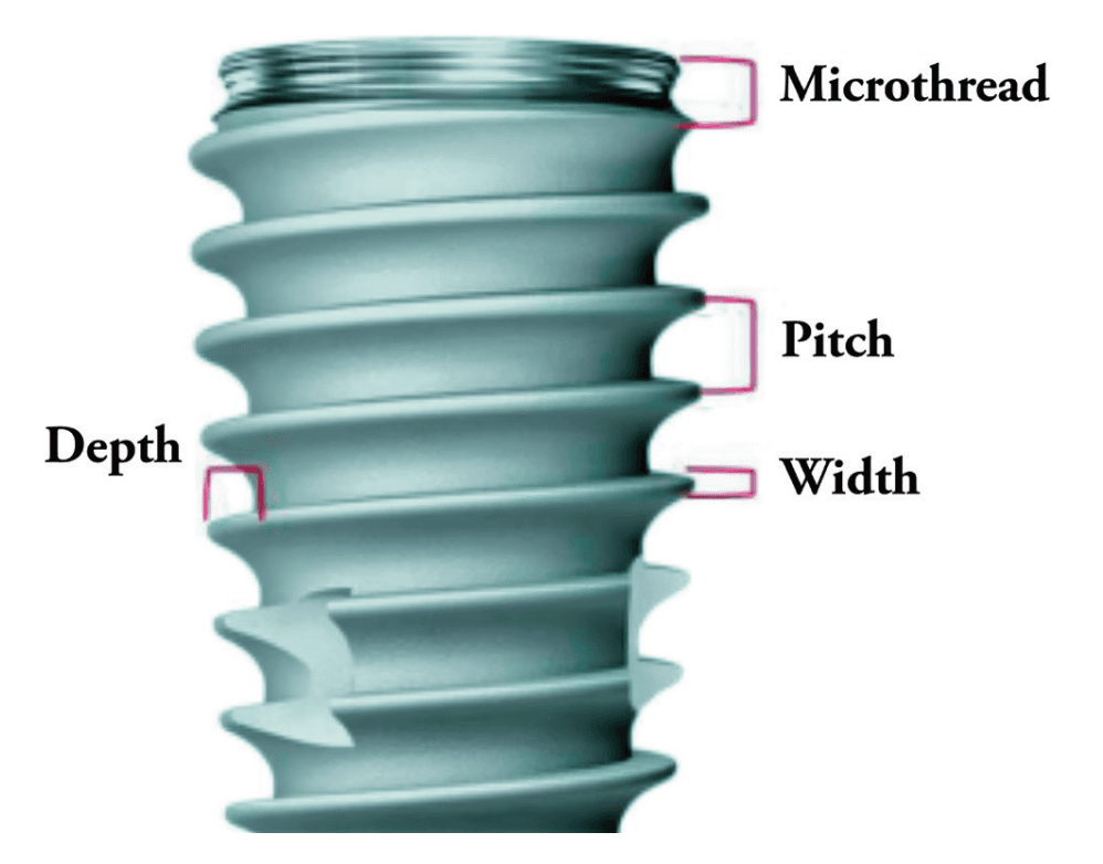
Implant design can play a significant role in the immediate-load process. Considerations include choosing an implant with appropriate width and length for the desired anatomical site (generally falls between 10 mm -15 mm in length and 3.5 mm -5.0 mm in width) and the use of a tapered implant design. Implants with deeper thread depths and shorter thread pitches can increase the bone-to-implant contact and increase primary stability5 (Figure 4 shows a visual of these terms). V-shaped threads are more aggressive and allow for greater stability of implants, while more square-shaped threads allow for greater distribution of stress and greater bone-to-implant contact.6 An implant design that is self-tapping is also advantageous for increasing primary stability.7 Although drilling protocols for osteotomies are guided by manufacturer’s recommendation, in general, primary stability can be increased when the osteotomies are under-prepared in width.8
Surgical techniques
After proper anatomic evaluation and prosthetic planning, it can be determined which techniques and implants can be utilized.
The traditional All-on-4 configuration is performed by placing two axial implants in the anterior jaw and two distally tilted implants in the posterior jaw in both the maxilla and the mandible. The posterior implants are placed tilted in order to 1) obtain sufficient anterior-posterior (AP) spread, 2) avoid disrupting anatomical structures, and 3) (which most pertains to this article) to increase the bone-to-implant contact for increased primary stability.10
Maxilla
In the maxilla, the areas of most common apical fixation include the apical bone of the anterior and premolar zones. Following the traditional All-on-4 protocol, the posterior-angled implants should aim to have their apices anchored in the point of maximum bone mass just lateral to the piriform rim and mesial to the anterior sinus wall. This area is termed the M-point by Ole Jensen.3
The anterior implants have slightly more options as they can either be placed axially, directed distally to the M-point, or directed anteriorly toward the point of maximum bone mass at the superior midline near the junction of the nasal crest and the vomer. This point is called the V-point, also termed by Jensen3 (Figure 5).

If more stability is needed, both the posterior as well as the anterior implants can slightly perforate and engage the cortical bone of the piriform rim for bicortical stabilization11 as seen in Figure 6.

Mandible
Similar to the maxilla, mandibular implants are commonly fixated to the apical bone of the anterior and premolar zones utilizing tilted distal implants and axially placed anterior implants. In certain circumstances, the length of these implants can extend as far as to the inferior border of the mandible to engage its dense cortical bone.3 An additional point of anchorage are implants placed behind the mental foramen. Typically there is limited bone height availability in these areas due to the proximity to the inferior alveolar nerve following alveoloplasty or due to atrophy. When enough vertical bone is available, shorter and wider implants can be axially placed in these retroforaminal positions.
Alternative alveolar sites for implant anchorage
When the degree of atrophy increases, other techniques can be utilized to obtain primary stability in biologically stable positions. The remainder of this article will focus on the techniques and protocols available for the maxillary jaw.

Palatal approach and palatal root
Two techniques that take advantage of the dense palatal bone of the maxilla are implant insertion via the palatal approach and implant insertion into the palatal roots of maxillary molars. “Palatal approach” focuses on placing the implant on the palatal side of the alveolar ridge in the presence of advanced buccolingual atrophy. These implants apically engage the dense bone of the hard palate.12 This will many times lead to thread exposure on the lingual side of the implant as seen in Figure 7. This exposed area should be in a position where the thick keratinized gingiva of the palate can passively cover the lingual threads while suturing. The palatal approach allows for implants to be anchored with sufficient primary stability in sites with narrow buccolingual dimensions.

Photos of Figures 9-11 contributed by Dr. Kyle Hargis
The second anchorage site to consider is the palatal root of the maxillary molars. If there is a maxillary molar present pre-operatively, and there is sufficient vertical bone height at this area post-alveoplasty, the palatal root can be utilized as an anchorage point (Figures 8-11). This implant will generally be shorter and wider (ex. 5 mm x 8 mm). If an implant is being placed into the palatal root, then generally the drilling protocol should be more focused on expanding and shaping the socket and starting with wider drills in preparation for the desired implant to be placed. This is different from situations where the interradicular bone of the maxillary molars are utilized, and the drilling protocol follows a more standard sequence.
Remote anchorage
In cases of severe maxillary atrophy, there are remote sites of implant anchorage that deviate from the traditional sites of the alveolar bone. These remotely anchored implants include pterygoid, trans-sinus, zygomatic, trans-nasal, and subperiosteal implants. These techniques require advanced training due to their increased degree of difficulty and should only be performed when clinically appropriate. Pterygoid, zygomatic, and trans-sinus implants will be generally discussed in this article. These descriptions serve as a basic understanding of these implants. Resources such as Dan Holtzclaw’s Remote Anchorage Solutions for Severe Maxillary Atrophy (Zygoma Partners, LLLP), Carlos Aparicio’s Advanced Zygomatic Implants: The ZAGA Concept (Quintessence Publishing), and many others can be studied if the reader would like a deeper didactic understanding and insight into remotely anchored implants.

Pterygoid implants
The pterygoid implant utilizes the dense bone of the pyramidal process of the palatine bone and the pterygomaxillary junction (pterygoid pillar) to gain primary stability in the posterior maxillary regions.13 These implants not only increase the amount of cumulative torque values, but also eliminate the posterior cantilever allowing there to be reduced stress on the distal mid-maxillary implants.14 The pterygoid implant is placed in a medial-superior-distal direction to allow for greater engagement of the pyramidal process and pterygoid pillar (Figures 12-14). Great care needs to be taken to avoid critical anatomical structures that are adjacent to this anchorage spot. These include the infratemporal fossa and the pterygopalatine fossa, both which contain vasculature that could be life threatening if severed. Precision is of importance when seeking to engage the desired target area of hard tissue and avoid hitting any vital anatomical structures that could lead to significant hemorrhage and complications. The pterygoid implant is a useful multifunctional tool to obtain primary stability in distal sites, increase the A-P spread, and eliminate the cantilever.

Zygomatic implants
Zygomatic implants are significantly longer implants which engage the dense bone of the zygoma and were originally placed to provide posterior support in the severely atrophic maxilla15 (Figure 15). These implants are indicated when there is little to no remaining bone height of the alveolar ridge as well as severe anterior pneumatization of the maxillary sinuses.15 Carlos Aparicio created the Zygoma Anatomy Guided Approach (ZAGA) in 2011 which serves as a guide for zygomatic implant planning with respect to patient specific anatomy of the zygoma and favorable prosthetic planning.15 As previously mentioned, the zygomaticomaxillary buttress is one of the several buttresses of the skull that provide a mass of cortical bone that can be used for predictable immediate loading. Although predictable, these implants should be reserved for severely atrophic cases and revisions as indicated.

Trans-sinus implants
Lastly, the trans-sinus implant can also be used to obtain primary stability in the midst of severe anterior pneumatization of the maxillary sinuses. With traditional All-on-4 configurations, the posterior implants are angled to the distal and are positioned just anterior to the anterior border of the maxillary sinuses to remain enclosed in bone. When the sinuses are significantly pneumatized anteriorly, the trans-sinus implant can be a suitable technique to establish posterior support. This implant is similar to the traditional All-on-4 distal implant; however, it intentionally penetrates the anterior portion of the maxillary sinus on its way to engage the cortical bone lateral to the nasal aperture (M-point) as seen in Figures 16 and 17. These implants have shown high success rates since first documented in 2012.16
Protocols
There are a vast amount of techniques to utilize different anatomical structures in order to obtain the primary stability needed for immediate load. With the multitude of approaches, it is up to the implant surgeon to select what approach to use for each case. In addition to Malo’s traditional All-on-4 protocol, several guidelines have been proposed as roadmaps for full-arch implant placement with a focus on engaging bone best fit for load bearing in prosthetically favorable positions.

Ole Jensen developed an immediate loading site classification for the maxilla utilizing four implants.3 His protocol classifies the maxilla into four groups based on the degree of atrophy. He describes the maxillary and mandibular jaws as Class A, Class B, Class C, or Class D in order from less-to-more jaw resorption (Figure 18). Jensen describes utilizing longer tilted implants to engage the dense bone of the maxilla, and as atrophy increases, the length and configuration of implants change accordingly.

The PATZI protocol is another approach described by Shouvik Ponnusamy, Juan Gonzalez, and Dan Holtzclaw which aims to improve cumulative torque values, AP spread, and prosthetic planning using a systematic algorithm17 (Figure 19). “PATZI” is an acronym for Pterygoid Anterior Tilted Zygomatic Implants. This protocol begins with placement of the pterygoid implant. The next step is implant placement in the anterior. These implants include axial, nasopalatine, piriform rim, or transnasal implants. Next is the placement of the tilted implant. These implants provide support for the mid-maxillary region and consist of either traditional All-on-4 tilted implants or trans-sinus implants. Lastly, if the tilted implants are not able to be placed, zygomatic implants are utilized in this region. As it relates to the implant’s apical position within the zygoma, a posterior-inferiorly placed zygomatic implant can be used for posterior prosthetic support, and an anterior-superiorly placed zygomatic implant can be used for more anterior prosthetic support. The PATZI protocol is a novel approach to mechanically anchoring implants into favorable positions and decreasing/eliminating cantilever stresses with fixed full arch maxillary rehabilitation.
In addition to the general treatment planning considerations for dental implants (medical history, occlusion, patient habits, soft tissue, etc.), the full-arch immediate-load treatment modality depends heavily on the ability to achieve adequate primary stability. The implant surgeon should be aware of predictable points of anchorage and should be able to identify and use these areas as indicated for each patient’s unique anatomy. Failure to have this knowledge could lead to a delayed loading of the prosthetic at best, or an aborted procedure with added time, procedures, and finances at worst. With proper training, experience, and knowledge, obtaining predictable and consistent primary stability is a goal that every full-arch surgeon should be able to achieve.
Author Info
 Leke Olowokere, DDS, FICOI, obtained his Doctor of Dental Surgery degree from Texas A&M College of Dentistry in Dallas, Texas. Following graduation, he completed a general practice residency at the Dallas VA Medical Center and has since devoted his practice to dental implantology, dentoalveolar surgery, and removable dentures. He has committed hundreds of hours toward continuing education and worldwide training with a focus in full-arch implant-supported rehabilitation all in order to best “restore health, wellness, and hope one smile at a time.” Dr. Olowokere currently practices in Springdale, Arkansas and serves as a mentor with Shared Practices Group, a nationwide DSO focused on full arch implantology.
References
- Gallardo YNR, da Silva-Olivio IR, Gonzaga L, Sesma N, Martin W. A Systematic Review of Clinical Outcomes on Patients Rehabilitated with Complete-Arch Fixed Implant-Supported Prostheses According to the Time of Loading. J Prosthodont. 2019 Dec;28(9):958-968. doi: 10.1111/jopr.13104. Epub 2019 Oct 18.
- Papaspyridakos P, Chen CJ, Chuang SK, Weber HP. Implant loading protocols for edentulous patients with fixed prostheses: a systematic review and meta-analysis. Int J Oral Maxillofac Implants. 2014;29 Suppl:256-270. doi: 10.11607/jomi.2014suppl.g4.3.
- Jensen OT. Complete arch site classification for all-on-4 immediate function. J Prosthet Dent. 2014 Oct;112(4):741-751.e2. doi: 10.1016/j.prosdent.2013.12.023. Epub 2014 May 13.
- Ghosh SG, Patra SK. Fractures involving bony orbit: A comprehensive review of relevant clinical anatomy. Translational Research in Anatomy, 2021;24(Suppl 1):100125. https://doi.org/10.1016/j.tria.2021.100125.
- Abuhussein H, Pagni G, Rebaudi A, Wang HL. The effect of thread pattern upon implant osseointegration. Clin Oral Implants Res. 2010 Feb;21(2):129-136. doi: 10.1111/j.1600-0501.2009.01800.x. Epub
2009 Aug 25. - Menini M, Bagnasco F, Calimodio I, Di Tullio N, Delucchi F, Baldi D, Pera F. Influence of Implant Thread Morphology on Primary Stability: A Prospective Clinical Study. Biomed Res Int. 2020 Aug 5;2020:6974050. doi: 10.1155/2020/6974050.
- Toyoshima T, Wagner W, Klein MO, Stender E, Wieland M, Al-Nawas B. Primary stability of a hybrid self-tapping implant compared to a cylindrical non-self-tapping implant with respect to drilling protocols in an ex vivo model. Clin Implant Dent Relat Res. 2011 Mar;13(1):71-78. doi: 10.1111/j.1708-8208.2009.00185.x.
- Degidi M, Daprile G, Piattelli A. Influence of underpreparation on primary stability of implants inserted in poor quality bone sites: an in vitro study. J Oral Maxillofac Surg. 2015 Jun;73(6):1084-1088. doi: 10.1016/j.joms.2015.01.029. Epub 2015 Feb 7.
- Ryu HS, Namgung C, Lee JH, Lim YJ. The influence of thread geometry on implant osseointegration under immediate loading: a literature review. J Adv Prosthodont. 2014 Dec;6(6):547-554. doi: 10.4047/jap.2014.6.6.547. Epub 2014 Dec 17.
- Taruna M, Chittaranjan B, Sudheer N, Tella S, Abusaad M. Prosthodontic perspective to all-on-4® concept for dental implants. J Clin Diagn Res. 2014 Oct;8(10):ZE16-19. doi: 10.7860/JCDR/ 2014/9648.5020. Epub 2014 Oct 20.
- Wu HC, Huang HL, Fuh LJ, Tsai MT, Hsu JT. Influence of implant length and insertion depth on primary stability of short dental implants: An in vitro study of a novel mandibular artificial bone model. J Dent Sci. 2024 Jan;19(1):139-147. doi: 10.1016/j.jds. 2023.05.019. Epub 2023 May 31.
- Andreasi Bassi M, Lopez MA, Andrisani C, Ormanier Z, Gargari M. Full arch rehabilitation in severe maxillary atrophy with palatal approach implant placement: a case report. Oral Implantol (Rome). 2016 Nov 13;9(3):115-122. doi: 10.11138/orl/2016.9.3.115.
- D’Amario M, Orsijena A, Franco R, Chiacchia M, Jahjah A, Capogreco M. Clinical achievements of implantology in the pterygoid region: A systematic review and meta-analysis of the literature. J Stomatol Oral Maxillofac Surg. 2024 Sep;125(5S1): 101951. doi: 10.1016/j.jormas.2024.101951. Epub 2024 Jun 19.
- Wilkirson E, Chandran R, Duan Y. Rehabilitation of Atrophic Posterior Maxilla with Pterygoid Implants: A 3D Finite Element Analysis. Int J Oral Maxillofac Implants. 2021 May-Jun;36(3):e51-e62. doi: 10.11607/jomi.8185.
- Aparicio C, Manresa C, Francisco K, Claros P, Alández J, González-Martín O, Albrektsson T. Zygomatic implants: indications, techniques and outcomes, and the zygomatic success code. Periodontol 2000. 2014 Oct;66(1):41-58. doi: 10.1111/prd.12038.
- Jensen OT, Cottam J, Ringeman J, Adams M. Trans-sinus dental implants, bone morphogenetic protein 2, and immediate function for all-on-4 treatment of severe maxillary atrophy. J Oral Maxillofac Surg. 2012 Jan;70(1):141-148. doi: 10.1016/j.joms.2011.03.045. Epub 2011 Jul 28.
- Ponnusamy S, Gonzalez J, Holtzclaw D. A Systematic Approach to Restoring Full Arch Length with Maxillary Fixed Implant Reconstruction: The PATZi Protocol. Int J Oral Maxillofac Implants. 2023 Oct 17;38(5):996-1004. doi: 10.11607/jomi.10153.
Stay Relevant With Implant Practice US
Join our email list for CE courses and webinars, articles and mores