Educational aims and objectives
This clinical article aims to present the protocols for applying the Axiom® TL implant and InLink® connection in All-on-4 treatment.
Expected outcomes
Implant Practice US subscribers can answer the CE questions by taking the quiz to earn 2 hours of CE from reading this article. Correctly answering the questions will demonstrate the reader can:
- Identify the surgical, technical, and restorative protocols for achieving success in this indication.
- Recognize the Axiom TL system and its parts.
- Observe a clinical case in which the Axiom TL system was used.
- Realize certain postoperative clinical controls.
- Observe the final bridge development phase of this process for this specific patient.
Dr. Jean-Baptiste Verdino, Jean-Michel Moal, and Gilles Giordanengo combine Axiom® TL implants, InLink Connection, and All-on-4 treatment for prosthetic rehabilitation.
Dr. Jean-Baptiste Verdino, Jean-Michel Moal, and Gilles Giordanengo discuss the protocols for a new “tissue level” implant system to establish how it improves prosthetic rehabilitation
Introduction
Treating complete maxillary edentulism with a screw-retained implant-borne prosthesis followed by immediate functional loading has become a standard treatment (Esposito, et al., 2013). The number and position of the implants can vary depending on the school and the physician; the All-on-4 technique (Malo, 2005), for example, is now reasonably accepted as a therapeutic option.
This technique uses four implants to support the future denture: Ideally, two are positioned at the lateral incisor, and the two posterior implants are positioned at the second premolar, angled so that they follow the anterior sinus wall (Szmukler-Moncler, 1998). Because of this, angulated abutments of 17° or 30° are generally used to correct the axis and have an emergence compatible with the future prosthesis (Rangert, et al., 2006).
This clinical case aims to present the use of a new kind of implant, which features tissue level positioning (meaning that the implant emerges at the gingival level, as opposed to the level of the bone), a flat connecting element, and a prosthetic locking system.
The Axiom® TL (Tissue Level) system
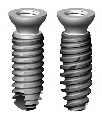
Axiom® TL implants (Anthogyr) are designed with a variable transgingival height (1.5 mm, 2.5 mm, and 3.5 mm) that ends in a flat connecting element. They are constructed from Grade 5 titanium with two styles of threading available (PX or REG), depending on bone density (Figure 1).
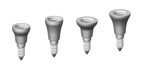
Below the threading, the implant narrows at the neck (Anthogyr’s “tissue favored design”), which is intended to promote epithelial connective attachment and primary healing (Hermann, et al., 2001; Atieh, et al., 2010; Bolle, et al., 2015). This shape is designed to result in better protection for the underlying bone and better resistance to peri-implantitis. The system also provides transgingival abutments called InLink® (Figure 2), which transform a bone level implant into a tissue level implant. The transgingival part comes in two diameters (4 mm and 4.8 mm).
The InLink connecting element allows for the creation of multiple-unit screw-retained prostheses. A locking system is integrated into the prosthesis, composed of a fastening lock and a retention ring (Figure 3). The flat connection can make positioning the prosthesis a delicate procedure, so a guiding system is available.

The retention ring is found in the cervical portion of the prosthesis within a specifically machined housing (Figures 4 and 5).
The InLink connection allows significant divergences from the implant axis to be corrected without the addition of intermediate abutments, as well as the integration of angulated screw channels up to 25° with narrowed screw channels. Because the connection is integrated into the prosthesis, there is no manipulation of the screw; the prosthetic is locked with a ball wrench (Figure 6).
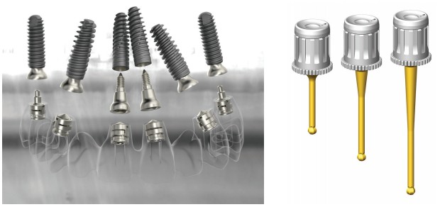
Creating a temporary prosthesis on InLink is easy because the temporary abutments come in both straight and angulated versions (25°) (Figures 7 and 8), which remove the decision about angulated abutments during surgery and delegate that choice to the laboratory. These can be delivered with fitting locks (green) for testing in the prosthesis in the mouth.

The green locks should be replaced with clinical locks (titanium in color) when the prosthesis is placed. Changing locks is simple with the dedicated instrument (Figure 9). Moreover, a laboratory clip is also included, which is designed to be screwed onto the replicas and avoids tedious screwing and unscrewing (Figure 10).
Clinical case
This case follows a 62-year-old female to demonstrate the clinical and restorative protocols for treatment using Axiom implants and the InLink connection. This patient presented with no significant medical history, complete maxillary edentulism, and partial mandibular edentulism (Figures 11 to 14).
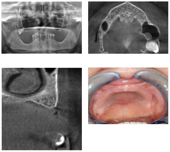
The mandible was planned for treatment first with a fixed cement-retained prosthesis. Because of the lack of bone in the area under the sinuses, an All-on-4 maxillary restoration was indicated with two implants under the nasal cavities and two angulated implants along the anterior sinus walls (bone in areas I and II, according to the Bedrossian classification) (Bedrossian, et al., 2008), followed by immediate loading.
The angulation of the distal implant offers several advantages:
- Places the implant between the anterior sinus wall and the palatal cortical bone.
- Using a longer implant naturally presents a larger surface for bone-implant contact, which gives sufficient primary stability and is therefore compatible with the immediate loading technique.
- Moves the emergence of the implant distally, thereby reducing the future cantilever (Aparicio, et al., 2010).
Immediate loading was planned to follow the surgery.
Preparing for immediate loading
After mandibular restoration, the patient models were mounted in the articulator, and esthetic testing was done, tested, and validated. Mounting in the articulator is a vital step to create a coherent occlusal plan.
A silicone key of this arrangement was produced, which was used to produce a radiological and surgical transparent resin guide, and a full arch with stock teeth ready to be joined to the future abutments.
The chosen teeth were filled with resin (VITAPAN® PLUS, Vita North America; Yorba Linda, California) to facilitate adjustment by drilling, and also because of wear and tear from the opposing teeth. The surgical guide was then perforated at the palate in the placement envelope for future implants. This had two goals:
- To guide surgery when the implants are positioned.
- To serve in the occlusion transfer following surgery.
Surgical phase
Local anesthesia was administered at multiple bilateral injection sites:
- high-tuberosity approach
- suborbital
- palatal
A full-thickness flap was created, and four 3.4 mm R Axiom TL implants (4.8 mm diameter) height 2.5 were placed: First, the subnasal mesial implant was placed with an infracrestal placement of the 0.5 mm implant threading. To place the distal implant as close as possible to the anterior sinus wall, a window was made on the anterior part of the maxillary sinus, and the topography of the anterior sinus wall was determined using a depth gauge (Figure 15). This allowed us to create an angulated drilling hole from the distal to the mesial and from the vestibular to the palatal.

As a result, the implant was positioned close to two areas of dense bone: the anterior sinus wall and the palatal cortical bone. This allowed the distal implant to be placed as far away as possible, as well as at the maximum anteroposterior distance, depending on the case in question (Figure 16). This position allowed us to reduce the degree of cantilever (Aparicio, et al., 2010), which was essential for the final bridge. In this case, the implant emergence was located around the first premolar. The cantilever would be definitively reduced for the provisional bridge without framework.
Drilling was carried out progressively with graduated drill bits increasing in diameter until the final drilling at 3 mm. Implants with a diameter of 3.5 mm were used here to preserve the maximum peri-implant bone, particularly toward the vestibular. This choice was supplemented by that of the trans-gingival part — in this case, 2.5 mm in height and 4.8 mm diameter.
This part is also available in 1.5 mm and 3.5 mm heights as a function of the peri-implant mucosa thickness and also in a narrower 4 mm diameter, which is useful in the incisor/canine area in cases of low resorption.
After inserting the four implants, H4 cylindrical healing screws were placed, and the tissues sutured with 4.0 resorbable sutures (Figure 17).
Tissue adjustment is usually carried out at this stage to optimize peripheral soft tissues, encourage the best possible gingival healing, and facilitate future hygiene procedures. This has the goal of placing as much keratinized gingiva around the head of the implant as possible without burying it too far. This operation is generally performed with a blade, but a tissue punch is often very pleasant to use (Figure 18).
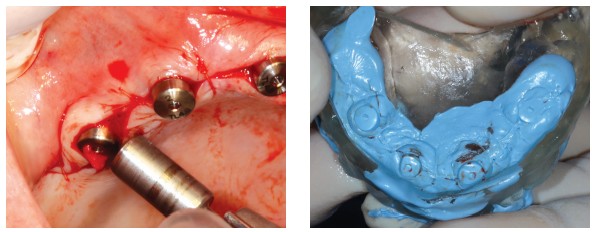
The surgical guide was then filled with silicone (Jet Blue™ Bite, Coltène/Whaledent Inc.; Cuyahoga Falls, Ohio) and repositioned in place. Once the material had set, the occlusion was recorded by applying Jet Blue Bite on the guide (Figure 19). The healing screws were removed, specific transfers were screwed, and their adjustment was checked radiologically (Figures 20A and 20B).
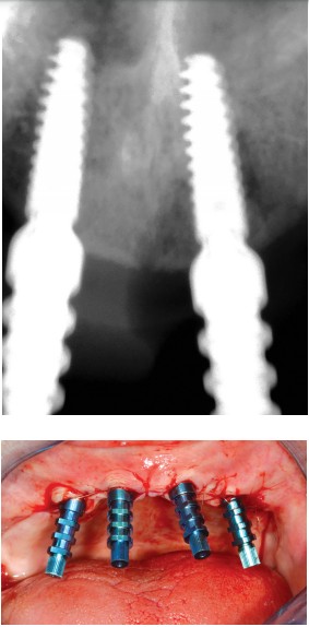
A plaster impression (Snow White™, Kerr; Brea, California) (Urstein, et al., 1991) was taken using a filmed impression-maker, specifically designed for this kind of impression (Figure 21). The use of this material is almost completely reliable in terms of the precision of the position of transfers and dimensional stability. After taking the impression, the transfers were unscrewed and the validity of the impression confirmed by the complete immobility of the transfers in the plaster.
Laboratory phase
The laboratory protocols begin by processing the impression. We start by applying an insulator (Vaseline®, Unilever; Englewood Cliffs, New Jersey), followed by screwing in tissue-level analogs. A false silicone gum is then poured. This facilitates obtaining an adequate emergence profile but needs to be removable to ensure the adjustment of future cylinders.
The model is then poured in GC FUJI ROCK® (GC America; Alsip, Illinois) dental stone. After unmolding, identical healing screws to the ones used in the mouth are placed in the replicas, and the surgical guide is repositioned on the model (taking care to avoid any interference with the plaster). The model can then be remounted on an articulator.
This is followed by screwing laboratory locks onto the replicas. These have an O-ring and, as the design phases progress on the model, allow the bridge to be placed and removed without having to do tedious screwing and unscrewing (Figure 22). The laboratory technician can then choose the appropriate provisional cylinders — straight and angulated — for emergence from the screw channel on the occlusal face of the future bridge. Contrary to the conventional rule, it is no longer the abutments that are chosen to be angulated during surgery, but instead the cylinders (Figure 23).

During the laboratory phase, the InLink fastening locks are removed, and the bridge can be positioned on the model with a simple clip. It is important to note the cylinders will be silanized (with a silicoater) and covered to the point of opacity. This not only eliminates any risk of the metal being visible, but also encourages a chemical bond (beyond the mechanical bond) between the resin and the cylinders and increases the solidity of the future temporary bridge.
The prepared cylinders can then be positioned and oriented, and their height reduced as necessary. The provisional dental arch, prepared previously, is adjusted around the cylinders with successive drilling, then joined to the cylinders with self-curing resin (Figure 24). The soft tissue is adjusted with the addition of dentin or pink-colored resin, as necessary. The finishing touches to the periphery are then applied. To avoid damaging the cylinder platforms, protective caps are clipped over the laboratory locks (Figure 25).

During this stage, toothbrushes are used in the form of mini-tunnels to adjust parts of each cylinder.
The bridge is repositioned on the model for the last occlusal adjustments. Then the technician replaces the clinical locks, taking care to include a guiding lock to facilitate clinical placement of the bridge. The guiding lock is longer along the screw and makes positioning the guide easier (Figure 26). Up to two can be used on the implants with minimal relative divergence.
The bridge should then be made passive, to minimize possible harmful forces on the implants. To do this, the bridge is screwed to 25Ncm on the working model, and the whole ensemble is placed in boiling water under pressure for 10 minutes, then allowed to air-cool for around 20 minutes.
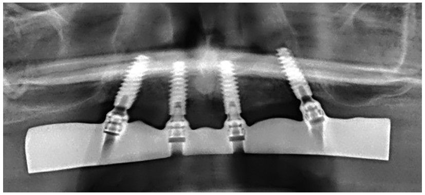
Passivity is verified by unscrewing the bridge and re-screwing it onto one of the replicas, and verifying it remains flat on the others. The bridge is then fitted into the mouth by alternating screws — first manually, then to 25Ncm — and the occlusal adjustment is finalized. A panoramic radiograph should then be taken to get a reference snapshot of the bone/implant situation and to check the exact fit of the cylinders on the implants (Figures 27 and 28).

Clinical controls
An initial check is made after the first week, occlusion is verified again, and the patient’s ability to brush and maintain adapted hygiene is confirmed. During the period of bone healing — a minimum of 4 months — a visit should be scheduled every 3 weeks with checkup points. Examples follow:
- Occlusion
- Hygiene
- Lack of pain and inflammation
- Lack of muscle spasms
Final bridge development phase
Following the 4-month healing phase in the absence of clinical or radiographic problems, the final bridge can start to be developed. Assuming that the esthetics and function of the provisional bridge are approved, they are reproduced in terms of the vertical dimension of occlusion, the shape and color of the teeth, and especially the external profile of the bridge, such that it allows for optimal hygiene.
In All-on-4 cases with significant levels of tissue resorption, the authors’ preference is for composite bridges with a titanium framework, stock-microfilled composite teeth (VITA PHYSIODENS®, Vita North America; Yorba Linda, California), and false gum made of resin.
The framework is created with CAD/CAM as a guarantee of solidity, reliability, passivity, and as a result, the ideal biological tolerance (Miyazaki, et al., 2009; Lops, et al., 2015). A new impression is then made to record the morphology of the healed soft tissue and the position of the implants. This impression uses the open impression technique, with pickup transfers. The chosen recording material is plaster because of its precision and significant dimensional stability.
It is processed rigorously under a microscope: New replicas are screwed on with the goal of guaranteeing the compliance and traceability of the future machined framework.
Two components are created:
- A plaster mold (Snow White), designed to validate the working model. If it can be screwed into without breaking, it can be considered to be passive, and the model is trusted (Figure 29).
- A resin mold, designed to record the occlusal relationship (Figure 30).
Each of these components is constructed on the temporary cylinders with adjusted diameters, either straight or angulated, as necessary. These are tested in the mouth. In the event that the plaster mold breaks, the impression is taken again.

The occlusion is recorded in wax (Moyco wax), and the models are mounted on a semi-adaptable articulator. Esthetic testing then follows, which is tested clinically; it should have the exact characteristics of the future bridge and the points to check are rigorous:
- Phonetic tests
- VDO
- Access to hygiene (use of a toothbrush)
- Occlusion
- Esthetics
The latter aspect in particular must be approved by the patient. After confirming these points, the bridge returns to the laboratory, and the framework design is created in software with an exterior envelope using a scanner, and according to the manufacturer’s protocol (Anthogyr) (Figure 31).

When the framework is received, the passivity of the framework and the scanned volume should be checked before moving to the finishing stages. The use of a primer (Bredent Silano-Pen procedure) is crucial to ensure that the titanium and the acrylic components bond chemically. Retaining clips are placed, just as during the creation of the temporary bridge in order to reposition the framework on the master model before pouring the resin for the tooth positioning key (Figure 32).
After curing (Figure 33), some touch-ups (filing, shaving, adding resin as necessary) may be performed. The occlusion is adjusted on the articulator, and the bridge is carefully polished. Before delivery, the clinical locks are put into place, two non-guiding and two guiding — critical for easy clinical placement. Without this, and because of the “flat” connection, the bridge insertion could be very difficult.
Final bridge delivery
After the temporary bridge is removed (which can be given to the patient on the working model in the event that a future touchup is necessary), the implant heads are cleaned with chlorhexidine.
The fastening locks are coated in chlorhexidine gel (Elugel), and the bridge is positioned, then screwed into place (Figure 34): first with the guiding locks, then the other two. The first screwing on is done by hand, and a first occlusion check is done by ensuring the occlusal concepts are respected (Mariani, et al., 2008):
- Anterior guiding during propulsion
- Slight anterior overjet to avoid locking when centered
- Protection for the lateral group
- Lack of balancing contacts
- Balance between the posterior areas when centered (check there is no overbite)
It is critical at this stage to immediately confirm the patient’s ability to brush around the implants (Figure 35). A panoramic radiograph should be taken to ensure the exact fit of the bridge on the implants (and also to check the peri-implant bone level) (Figure 36). Final screwing to 25Ncm can be carried out with a torque wrench, and the holes of the access channels filled with composite.
Checkups should be planned at 1 week, 3 weeks, and every 3 months for the first year. After 1 year, a new panoramic radiograph should be taken to verify bone stability and adaptation, and that nothing has come unscrewed. After that, a biannual visit is recommended.
Discussion
The use of this new concept offers considerable advantages, both biological and technical.
Biological
The design of these implants with tissue-level placement improves primary healing and stability in peri-implant soft tissue (Hermann, et al., 2001; Bolle, et al., 2015). Similarly, it results in an excess of connective tissue above the crestal bone because the implant’s neck design (the aforementioned “tissue-favored design”) provides better protection for the underlying bone and a lower rate of peri-implantitis (Atieh, et al., 2010).
This design involves a learning curve in the choice of height for the transgingival part, which comes in 1.5 mm, 2.5 mm and 3.5 mm, and sometimes requires adjustment of the soft tissue — thinning them, on occasion. However, the designer planned for the InLink abutments, which are able to transform a conventional bone level implant to a tissue level, and, therefore, allows for easier management, particularly in esthetic areas.
Technical
Innovation is significant here too. The flat connection allows the implants to be inclined and eliminates the tedious choice of angulated abutments, which were classically at 18° and 30°. Screwing on with the locks, guiding or not, is surprising but very easy. The fact that these locks are on the bridge itself facilitates the positioning procedures. Changing these locks and their removal and positioning during the laboratory phase is facilitated by a dedicated instrument.
The laboratory clips save precious time by avoiding the tedious screwing and unscrewing steps of bridge development at both temporary and final stages. The use of a ball wrench allows a part to move up to 25° from the axis of the cylinder compared to the implant. This is very useful in the case of angulated implants, but also allows for a certain freedom in positioning access channels on the occlusal face.
Conclusion
This new concept is a significant improvement in the treatment of edentulism with implant-borne prostheses. Beyond a simplification of the surgical steps, particularly by eliminating the choice of abutments, it offers significant biological advances, in terms of primary healing and maintaining medium-term and long-term peri-implant health. Moreover, these technical tricks greatly facilitate the prosthetic phases. This concept also has a place in the treatment of partial edentulism (where the ability to have angulated screws is often a major asset). The fact the physician no longer has to interfere with the bone-implant interface during impression-taking and testing procedures guarantees security and respect for peri-implant tissues.
After reading about Axiom® TL implants, see Dr. Moss Osman’s treatment of a patient with worn and damaged teeth with All-in-4. https://implantpracticeus.com/ce-articles/treating-edentulous-patients-using-the-all-on-4-treatment-concept/
References
- Aparicio C, Perales P, Rangert B. Tilted implants as an alternative to maxillary sinus grafting: a clinical, radiologic, and periotest study. Clin Implant Dent Relat Res. 2001;3(1):39-49.
- Atieh MA, Ibrahim HM, Atieh AH. Platform switching for marginal bone preservation around dental implants: a systematic review and meta-analysis. J Periodontol. 2010;81(10):1350-1366.
- Bedrossian E, Sullivan RM, Fortin Y, Malo P, Indresano T. Fixed-prosthetic implant restoration of the edentulous maxilla: a systematic pretreatment evaluation method. J Oral Maxillofac Surg. 2008;66(1):112-122.
- Bolle C, Gustin MP, Fau D, Exbrayat P, Boivin G, Grosgogeat B. Early peri-implant tissue healing on 1-piece implants with a concave transmucosal design: a histomorphometric study in dogs. Implant Dent. 2015;24(5):598-606.
- Esposito M, Grusovin MG, Maghaireh H, Worthington HV. Interventions for replacing missing teeth: different times for loading dental implants. Cochrane Database Syst Rev. 2013;28(3):CD003878.
- Hermann JS, Cochran DL, Buser D, Schenk RK, Schoolfield JD. Biologic Width around one- and two-piece titanium implants. Clin Oral Implants Res. 2001;12(6):559-571.
- Lops D, Bressan E, Parpaiola A, et al. Soft tissues stability of CAD-CAM and stock abutments in anterior regions: 2-year prospective multicentric cohort study. Clin Oral Implants Res. 2015;26(12):1436-1442.
- Malo P, Rangert B, Nobre M. All-on-4 immediate-function concept with Brånemark System implants for completely edentulous maxillae: a 1-year retrospective clinical study. Clin Implant Dent Relat Res. 2005; Suppl 1:S88-S94.
- Mariani P, Margossian P, Laborde G. Choix d’un concept occlusal en implantologie. Stratégie Prothétique. 2008; 8(1):5-13.
- Miyazaki T, Hotta Y, Kunii J, Kuriyama S, Tamaki Y. A review of dental CAD/CAM: current status and future perspectives from 20 years of experience. Dent Mater J. 2009;28(1):44-56.
- Rangert B, Aparicio C, Malevez C, Bedrossian E, Renouard F, Malo P, Calandriello R. Graftless rehabilitation of the atrophied maxilla – tilted implants, short implants and immediate function. In: Jensen OT, (ed). The Sinus Bone Graft. 2nd ed. UK: Quintessence Publishing; 2006.
- Szmukler-Moncler S, Salama H, Reingewirtz Y, Dubruille JH. Timing of loading and effect of micromotion on bone dental-implant interface: review of experimental literature. J Biomed Mater Res. 1998;43(2):192-203.
- Urstein M, Fitzig S, Moskona D, Cardash H. A clinical evaluation of materials used in registering interjaw relationships. J Prosthet Dent. 1991;65(3):372-377.


