Changing paradigms in implant dentistry

Continuing Education (CE)

The continuing education article below is available to Implantologists and general dental practitioners who perform implants.

In order to earn continuing education credits with our publication, you must be a paid subscriber of Implant Practice US and complete a short quiz about the content of the article.

Earn up to 16 online dental CE credits per year! Purchase a subscription now.

Dr. Ashok Sethi examines how the advent of technology has improved the options available for patients and clinicians alike

Figures 1-2: Preoperative view of total overclosure with traumatic occlusion. Interactive planning on the three-dimensional image using the SIMPLANT software. Each implant position can now be transferred to a stereolithographic model constructed from CT scan data. In addition, a drill guide can be fabricated from the same data, which will transfer the implant position from the planning directly to the mouth. The ExpertEase™ guided surgery system (Dentsply Implants) permits precise positioning in terms of angulation as well as depth

Human evolution is progressing at an exponential rate — something that is reflected in all human endeavors, including implant dentistry. This article aims to address the changes that have taken place within this field, consider the way they have impacted the way we work, and look at the benefits this has brought for our patients.

In modern implant dentistry, conceiving the end result before embarking on treatment has become easier, making it possible for both the patient and clinician to have an idea of the direction in which they are travelling. This article will specifically address the application of three-dimensional imaging, stereolithography, and CAD/CAM technology in the current practice of implant dentistry. Treatment carried out in stages, as well as the immediate replacement of failing teeth will be addressed.

Backward planning (forward thinking)
Conceiving the end result before embarking on treatment requires a number of stages, both technical and clinical. The key is in starting off with a realistic diagnostic preview (Figure 9) and transferring this information from one stage to the next and between the laboratory casts and the mouth. Three-dimensional imaging coupled with an interactive software program (SIMPLANT®, Leuven, Belgium; DENTSPLY Implants) greatly increases the accuracy and predictability with which the treatment can be completed (Sethi and Kaus, 2012).

Figures 3-5: Stereolithographic model is a replica of the maxilla and fabricated from the CT scan. Implant analogs have been inserted and abutments selected and customized. The transitional restoration based on the diagnostic preview (waxup) will be supported by the abutments. The connection of the transitional restoration to the abutment is via a prefabricated acrylic sleeve. The implants have been inserted into the maxilla. The preselected abutments have been attached and are visible in perfect parallelism and alignment to each other. These have been transferred from the stereolithographic model. The definitive porcelain fused to precious metal alloy can be seen. Note the closing scheme, which has been transferred from the diagnostic preview

Educational aims and objectives
This article aims to address the application of three-dimensional imaging, stereolithography,
and CAD/CAM technology in the current practice of implant dentistry.
Expected outcomes
Implant Practice US subscribers can answer the CE questions to earn 2 hours of CE from reading this article. Correctly answering the questions will demonstrate the reader can:

  • Realize how new technologies have improved available treatment options.
  • Recognize how position and the dimensions of the implants can be decided upon with technology.
  • Identify how an interactive software program can greatly increase the accuracy and predictability with which the treatment can be completed.
  • Realize how to utilize diagnostic imaging and transfer of tooth position data for immediate implant patients.
  • Realize how CBCT, stereolithography, and CAD/CAM are key elements in the immediate implant process.

Immediate replacement of failing teeth
Staged treatment is highly predictable. However, recent observations and developments in surface technologies have made it equally predictable to place implants immediately and bring them into function at the same time. This is also very attractive for patients because of the reduction in the number of surgical appointments. Most importantly, this provides the patient with a very attractive option of having the failing teeth removed and the new teeth implanted at the same time, albeit with a provisional restoration. The same process of diagnostic imaging and transfer of tooth position data can be carried out for a patient with failing teeth where there is a need for immediate placement of these teeth with implants.
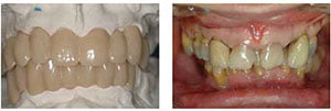
Figure 6: Diagnostic preview of proposed esthetic outcome and occlusal scheme; Figure 7: Preoperative view of malpositioned teeth and overclosed intermaxillary relationship

The position and the dimensions of the implants required for rehabilitation of the patient can be decided upon within the SIMPLANT program derived directly from CBCT data. This information can be transferred to a drill guide, which will enable the placement of the implants in the correct position and depth. This is facilitated by the use of stereolithographic models made directly from CT scan data. This, of course, enables the fabrication of the transitional restorations directly on the stereolithographic models. At the same time, selection of the abutments can be carried out based on the selected tooth position.

CAD/CAM technology

Figure 8: Showing the transfer of information from the diagnostic preview to the mouth in the form of a provisional metal-acrylic bridge, supported by selected teeth. Note the change in tooth position and intermaxillary relationship; Figure 9: Cone beam CT scan. Interactive planning using the SIMPLANT software showing the positioning of the implants within the available bone as well as the selection of the abutments, which lie within the prosthetic envelope

The first stage is to construct an accurate cast of the abutments in the patient’s mouth (Assif, et al., 1996; Assif, et al., 1999). It is then possible to scan the cast with the abutments, using a digital scanner. At the same time, the diagnostic preview (waxup) indicating the position of the planned teeth needs to be scanned.

Once the desired tooth position and the abutment position and shape have been scanned, it is possible to fabricate a prosthetic framework by milling it from a number of materials. These may be titanium, zirconium oxide, or a chrome-cobalt alloy. Porcelain or acrylic can then be veneered onto the framework.

Case studies
The cases studies illustrate how three-dimensional imaging, stereolithography, and CAD/CAM technology can be put in practice in different clinical situations.

Figure 10: Intraoperative view showing the implants inserted into preselected positions decided upon using the cone beam CT scan; Figure 11: Transitional restoration made from data transferred from the diagnostic preview and the provisional metal acrylic frustration. The transitional restoration is supported by the abutments. It is used to develop soft tissue contours for a natural emergence profile
Figure 12: Intraoral view of the abutments on completion of soft tissue healing. The contours developed by the transitional restoration are visible. Note that the abutments lie within the prosthetic envelope and are aligned to each other

Case 1 (Figures 1-5) depicts the management of a patient whose medical condition indicated the reduction of the number of interventions to a minimum.

Case 2 (Figures 6-13) depicts the management of a patient with failing teeth who required a change in the appearance as well as the occlusal scheme to achieve a better esthetic and functional outcome.

Case 3 (Figures 14-20) depicts the fabrication of a framework using CAD/CAM technology, which enables a more accurate fit to be achieved than a framework made by conventional casting technology (Takahashi and Gunne, 2003).

Figure 13: Definitive restoration. Note the naturally contoured soft tissue emergence profile
Figure 14: Four abutments, attached to implants in the interforaminal region, can be seen. Impressions of these are taken using the open-tray technique, the accuracy verified, and master cast constructed; Figure 15: The master cast with abutment analogs is visible. This has been constructed from a verification jig. This will be scanned along with the diagnostic preview. Both the master cast and the diagnostic preview will be sent to the scanning center; Figure 16: The diagnostic preview will be sent to the scanning center along with the master cast. The scanned data will then be used to construct the metal (chrome-cobalt) framework
Figure 17: The diagnostic preview scanned. The contour of the try-in has been digitally reduced to allow for space for the addition of the veneering material, which may be either porcelain, composite, or acrylic; Figure 18: The metalwork can be seen seated on to the master cast. Provision has been made for the veneering of the porcelain; Figure 19: The fit surface of the framework — with the porcelain fused to it visible
Figure 20: The definitive screw-retained restoration is visible. The main advantage of CAD/CAM technology is that it allows the fabrication of the metal framework, which is more likely to fit accurately than a conventional cast framework

Author Info

Ashok Sethi, BDS, DGDP, MGDS (RCS Eng), FFGDP DUI (Lille), Specialist in Oral Surgery, Specialist in Prosthodontics, has been practicing the art and science of implant dentistry for over 35 years. He is an honorary life member of the ADI and is presently director of the PID – The Academy (www.pid academy.org.), which focuses on teaching all aspects of practical implant dentistry.

References

  1. Assif D, Marshak B, Schmidt A. Accuracy of implant impression techniques. Int J Oral Maxillofac Implants. 1996;11(2):216-222.
  2. Assif D, Nissan J, Varsano I, Singer A. Accuracy of implant impression splinted techniques: effect of splinting material. Int J Oral Maxillofac Implants. 1999;14(6):885-888.
  3. Sethi A, Kaus T. Practical Implant Dentistry. The Science and Art. 2nd ed. London: Quintessence Publishing Co. Ltd.; 2012.
  4. Takahashi T, Gunne J. Fit of implant frameworks: an in vitro comparison between two fabrication techniques. J Prosthet Dent. 2003;89(3):256-260.

SUBSCRIBE TODAY

Implant Practice US is a leading dental journal and publication for dental implantology continuing education, oral implantology case studies, and more. Subscribe to Implant Practice US today!

ONLINE DENTAL CE

Earn dental continuing education credits as an Implant Practice US subscriber. Log in for online dental CE credits now!

Other Dental Publications

AGD PACE MedMark White

SUBSCRIBE TODAY

Implant Practice US is a leading dental journal and publication for dental implantology continuing education, oral implantology case studies, and more. Subscribe to Implant Practice US today!

ONLINE DENTAL CE

Earn dental continuing education credits as an Implant Practice US subscriber. Log in for online dental CE credits now!

Other Dental Publications

Copyright © 2024 Orthodontic Practice US - Dental Journal and Online Dental CE | MedMark LLC
15720 North Greenway Hayden Loop, Suite #9 Scottsdale, AZ 85260 | All rights Reserved | Privacy Policy | Terms & Conditions

Shopping Cart
Scroll to Top